
RFID on Metal: Ferrite Backing Thickness and the Read Range Budget
Smart Card Manufacturing Notes
RFID on Metal: Ferrite Backing Thickness and the Read Range Budget
Published: November 20, 2026 | ZOWINDA Application Engineering
An RFID label that reads at six metres on a cardboard box will read at well under one metre on a steel cabinet, and nothing about the tag has changed. The metal is not blocking the field; it is participating in it. Understanding what a conductive surface does to the loop antenna is what separates an anti-metal construction that survives qualification from one that quietly underperforms for years, and the ferrite sheet that fixes it is bought by thickness, which is bought by cost.
What the Metal Actually Does
Place a conductive plane close behind a loop antenna and three things happen at once. First, the plane acts as a mirror that inverts the magnetic moment: the image current induced in the surface runs in the opposite sense to the antenna current, and the two fields cancel in the far direction. The effective radiation resistance of the small loop collapses toward zero. Second, the eddy currents flowing in the real, finite-conductivity metal dissipate energy as heat, which drags the quality factor of the antenna down. Third, the antenna now sits a fraction of a millimetre from a large conductor, so its parasitic capacitance rises and the resonant frequency shifts. The chip sees less field and a mistuned match at the same time, which is why the failure is not marginal but total.
The ferrite sheet is the classical answer for 13.56 MHz tags because it attacks all three mechanisms with one part. A high-permeability, low-loss magnetic material inserted between the antenna and the metal gives the loop flux a high-reluctance-free path to close through, restoring the effective inductance and pushing the image current deeper into a region that no longer couples to the antenna. What matters is not the physical thickness of the sheet alone but its magnetic thickness, the product of permeability and dimension, because the metal sees the sheet through that product. The same logic explains why a magnetically thin sheet bought on price performs like no sheet at all.
The thickness budget behaves like most engineering budgets: the first increment buys the most. Going from a bare tag on steel to a tag with a fraction of a millimetre of proper ferrite typically recovers the majority of the lost range, because the image-current cancellation, the worst mechanism, is largely removed. Increments beyond that still help, but each returns less, and beyond a few tenths of a millimetre the residual losses are eddy-current heating and antenna mistuning that no further ferrite will fix. At that point the remaining budget is better spent retuning the antenna with the sheet in place, because ferrite also shifts the resonant frequency downward and a construction that resonates on the bench may sit low once mounted.
Two consequences follow for anyone specifying these constructions. An anti-metal tag is tuned for a different environment from a free-space tag, so a design optimised on steel will read measurably worse in air, and a qualification programme that only tests one state will certify the wrong one. And the ferrite sheet is a ceramic: it is brittle, it is sensitive to the flexing and pressure of lamination and bending, and its permeability drifts with temperature, so the mechanical and thermal qualification is not optional decoration but part of the RF specification.
Specifying an Anti-Metal Construction in Five Steps
- Define both mounting states before the first prototype. Write down the on-metal and free-space geometries the product must serve, including the minimum steel mass behind the tag. A sheet designed against a thick cabinet behaves differently on a thin bracket, and the specification should name the worst case, not the typical one.
- Select the sheet class by permeability and loss, not by price. Ask the supplier for the real part of permeability and the loss tangent at 13.56 MHz, not only a nominal grade name. A sheet with attractive permeability but high loss converts the recovered signal into heat inside the sheet itself.
- Budget thickness against the range you actually need. Start with the smallest sheet thickness that recovers the required range in the worst mounting state, and add margin in quarter-steps. Each increment past the knee of the curve costs money and brittleness for diminishing returns.
- Retune and verify with the metal present. Trim the antenna matching with the ferrite and the steel both in place, then re-check the free-space state. Record both resonant frequencies; if they have drifted apart beyond the bandwidth of the chip, the design is too specific to one environment.
- Qualify mechanically and thermally like an RF part. Run the sheet through the real lamination or bonding pressure, bend it if the product bends, and sweep temperature while monitoring resonance. A cracked or thermally drifting sheet is a field failure that no RF test on a new sample will predict.
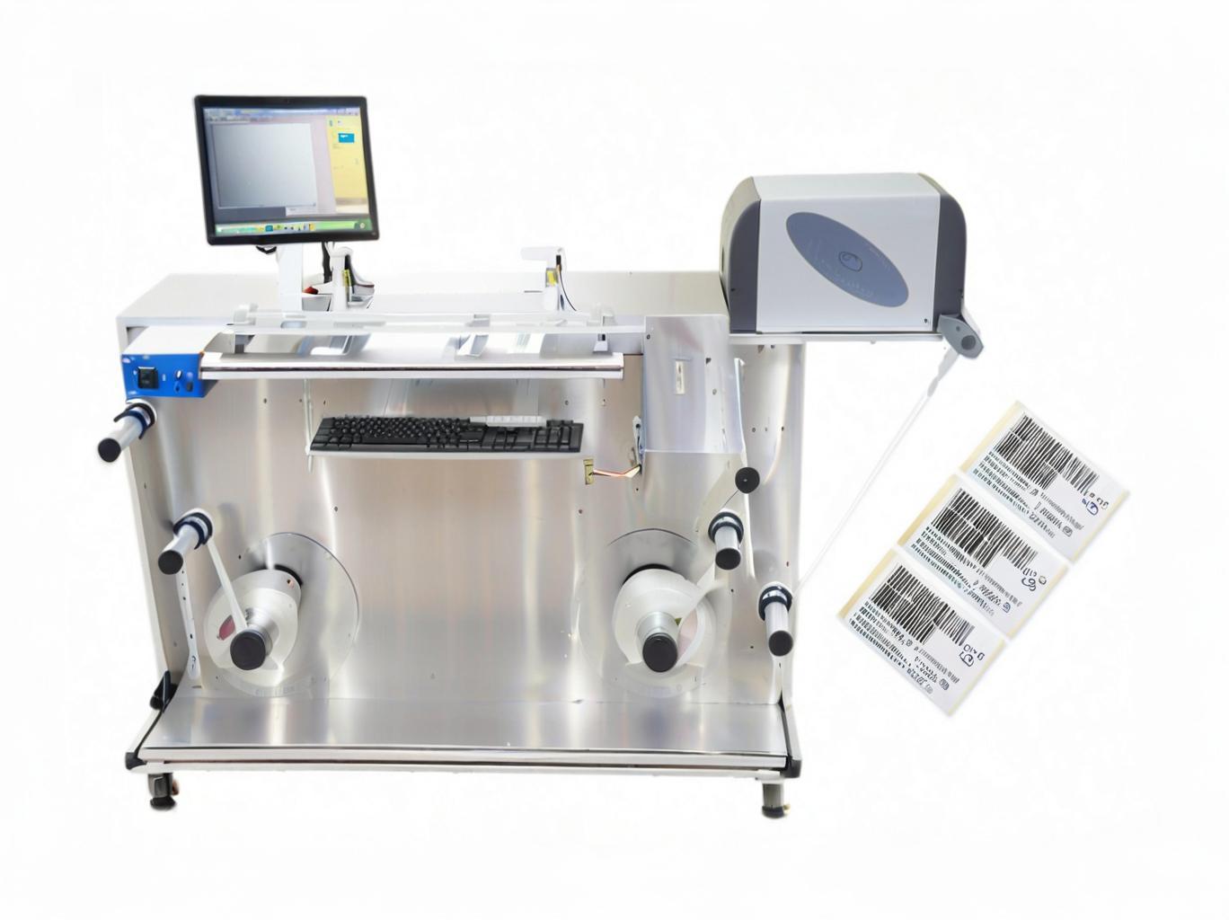
Encoding and verification under controlled conditions; an anti-metal construction must be verified in its final mounting geometry, not only on the bench. Equipment: RFID Label Detecting and Encoding Machine.
What a Good Anti-Metal Design Gets Right
✓ Specified by the magnetic thickness product
Permeability times dimension, with loss tangent as a companion limit, is the quantity that predicts behaviour. Thickness alone does not, and datasheets that quote only millimetres are incomplete.
✓ Antenna trimmed with the metal in place
The final resonance is set in the mounted state, then cross-checked in air. A construction tuned only on the bench is tuned for the bench.
✓ Loss tangent treated as a specification
A limit on the loss tangent keeps the sheet from eating the very margin it was installed to recover, and makes alternative suppliers comparable on physics rather than on price.
✓ Qualification covers both environments
On-metal and free-space ranges are measured and accepted separately, so nobody discovers after launch that the anti-metal tag is a poor free-space tag.
Reference Values for a Metal-Mount HF Construction
Reference bands for 13.56 MHz contactless tags mounted on steel or aluminium. Actual values depend on sheet grade, antenna topology, chip threshold, metal conductivity and geometry, and must be confirmed by measuring your own construction in its final mounting state.
Where the Construction Applies
Any tag whose service environment includes a conductive surface behind or beside the antenna:
- Tool and gauge tracking on steel cabinets, racks and machining fixtures
- Returnable metal containers and racks in closed logistics loops
- IT asset labels installed inside metal server chassis and racks
- Pipeline, valve and flange identification in process plants
- Automotive assembly jigs and metal-bodied returnable trays
Frequently Asked Questions
Can I just use a thicker foam spacer instead of ferrite?
At UHF, yes, often: a foam spacer of a few millimetres combined with a patch-style antenna is the standard metal-mount answer and is cheaper than ferrite. At 13.56 MHz a spacer alone does not restore the magnetic path of a small loop, so the ferrite sheet remains the standard construction; a spacer only adds distance and bulk without fixing the image-current cancellation.
Does the ferrite sheet survive card lamination?
Sintered sheets are brittle and can crack under concentrated pressure or sharp bending. Pre-cut sheets with rounded edges, controlled lamination pressure and a bend test on the finished product are the practical safeguards. A cracked sheet can lose RF performance without any visible exterior defect.
Why does the same tag read further once the metal is painted?
Paint adds a thin dielectric layer and a little spacing, which nudges the antenna slightly away from the surface and slightly changes the loading. The effect is real but small; it never substitutes for the ferrite sheet, and it disappears again the first time the tag is mounted on bare metal.
Next Step
More equipment in this range is listed on the ZOWINDA CardMachine product page, and related application notes appear in our Industry News section.
Related reading:
- RFID in Wet Environments: Dielectric Loading, Detuning and the Fixes That Hold
- Read Range Test Uncertainty: Why Two Laboratories Disagree on the Same Card
- Contactless Card Read Range: Diagnosing Antenna Resonance and Detuning
- Dual-Interface Ferrite: Why Sheet Thickness Beats Permeability on the Datasheet
- Card Face Printing and Read Range
- Printed Antenna Tolerance: Which Dimension Actually Moves Resonance
Ready to boost your production efficiency?
Contact us for a tailored solution and quotation on inlay production, card testing and personalisation equipment.
Email: info@zowinda.com
WhatsApp: +86 186 2085 0485
 Read Range Test Uncertainty: W
 RFID in Wet Environments: Diel
 RFID on Metal: Ferrite Backing
 Booklet Spine Adhesive: Why Fl
Please contact us with your request
We are ready to answer your questions.