
Card Face Printing and Read Range: Where Ink and Overlay Sit in the Stack
Smart Card Manufacturing Notes
Card Face Printing and Read Range: Where Ink and Overlay Sit in the Stack
Published: November 18, 2026 | ZOWINDA Application Engineering
The printed face of a contactless card is usually treated as decoration, and read range is treated as the antenna designer's problem. That split works until a card that read perfectly from a bare inlay sample fails at the reader after lamination and printing. The face is not a cosmetic layer sitting on top of the electrical design; it is part of the dielectric stack that the antenna resonates through, and every printed pass adds thickness and chemistry directly above the conductor.
The Antenna Is Never Alone in the Stack
A finished contactless card is a laminated sandwich: a core carrying the antenna, an overlay on each face, and on the printed side a sequence of primer, ink layers, varnish or spot coating, and on many cards a metallic foil, hologram patch or security print. Above the antenna conductor the total dielectric thickness is typically sixty to one hundred and fifty micrometres, made up of overlay film, adhesive, ink and coating. Each of those layers has a relative permittivity between roughly two and four and a loss tangent between one and three percent at 13.56 MHz, and all of them sit in the near field of the antenna, which is what determines the parasitic capacitance that fixes the resonant frequency.
Adding dielectric above a planar antenna raises the effective permittivity around the conductor, raises inter-turn capacitance, and therefore lowers the self-resonant frequency. The size of the effect scales with the thickness and permittivity of what was added, which is why a full face stack can pull a card down by several hundred kilohertz against the bare inlay it was tuned on. That is not a defect, it is arithmetic. It only becomes a field failure when the card design has no margin left to absorb it, or when the printed stack changes between lots without anyone re-qualifying the card.
The far more violent variable is pigment chemistry rather than colour. Conventional process inks are dielectric and mostly benign, but metallic inks, hot-stamp foil, metallised transfer film and silver-loaded conductive inks are not. A metallic layer above an antenna behaves as a shorted turn: it couples to the antenna, absorbs energy, collapses the quality factor and detunes the card by megahertz rather than kilohertz. Carbon-black inks sit in between, mildly conductive and lossy. This is why a design review that approves artwork by looking at a proof is worthless: a decorative silver band across the lower third of a card can cost more read range than doubling the overlay thickness.
Moisture is the third variable and the one that fails seasonally. Paper-faced and some coated cards take up water, and water has a permittivity near eighty. A card qualified in a dry plant can measure a different resonance in a humid warehouse, and the shift is reversible, so it never appears in a bench test that runs in one room. If a market reports that cards work in the morning and fail in the afternoon, the print stack and its moisture content belong on the suspect list next to the readers.
How to Qualify a Face Stack Instead of a Proof
- Write the stack up as a table before artwork is approved. List every layer above the conductor with nominal thickness, relative permittivity and loss tangent: overlay, adhesive, primer, each ink pass, varnish, foil, label. If a layer has no number, it has no business being in a card that has to read at a specified distance.
- Approve artwork against a keep-out map, not a visual. Mark the antenna footprint on the artwork file and restrict it to dielectric inks and coatings. Foil, metallised transfer and conductive inks go outside the keep-out, and any exception has to be measured, not argued.
- Measure resonance on finished cards from a real lot. Use a frequency tester on laminated, printed cards taken across the sheet, not on the inlay and not on one hand-picked sample. Record mean and standard deviation, because the acceptance question is how many cards fall outside the window, not whether one card passes.
- Set the window from the reader population you actually ship into. The card has to work at the weakest reader in the field, not at the bench reader. Derive the lower and upper resonance limits from that reader plus the metal detuning expected in use, then check the printed lot distribution against it with margin.
- Treat ink, foil, overlay and lamination recipe changes as product changes. A new ink supplier, a different pigment batch, a thicker overlay film or a new laminator setpoint all move the resonance. Require a first-article measurement of frequency and read range before a changed lot is released, and keep the numbers with the lot record.
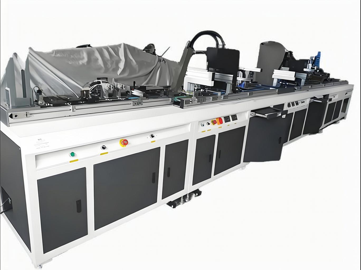
Printing on the face is dielectric engineering: each pass adds thickness and chemistry above the antenna. Equipment: DOD Drop-on-Demand Card Printing System.
Rules That Keep the Face Electrically Neutral
✓ Colour is free, chemistry is not
Four-colour process inks and standard varnishes can be chosen on appearance. Metallic pigments, foil and conductive inks cannot, because they interact with the antenna field rather than passing through it.
✓ Spend thickness where there is no antenna
If a card needs heavy ink coverage, varnish build or a thick patch, put it away from the antenna footprint. Thickness over the conductor is a cost; thickness elsewhere is decoration.
✓ Keep a resonance margin, not a single target
Design so that a few hundred kilohertz of print and lamination drift still lands inside the acceptance window. A card tuned to the exact carrier frequency has nowhere to go when the stack changes.
✓ Test the humid case once, then decide
Condition printed cards at high humidity and re-measure resonance and read range. If the shift is significant, specify the protective overlay and the storage conditions rather than discovering it in a customer complaint.
Reference Values for a Printed Face Stack
Typical reference bands for 13.56 MHz contactless cards with a printed inlay antenna and 0.76 to 0.84 millimetre bodies. Actual values depend on antenna geometry, overlay construction, ink system and reader design, and must be confirmed by measuring your own finished cards against your own reader population.
Where the Face Stack Question Applies
The same reasoning applies to any product where printed material sits above an antenna or a coupling element:
- Contactless payment and transit cards with full-face print, foil and holograms
- Dual-interface cards where the contact plate and the antenna share one body
- NFC tags and labels where the printed layer is a large fraction of the total thickness
- Event, access and membership cards with heavy spot colour or metallic effects
- Cards carrying security print, optically variable patches or hot-stamp panels
Frequently Asked Questions
Does a glossy varnish reduce read range?
By itself, a few micrometres of clear coating shifts resonance by tens of kilohertz, which is normally absorbed by design margin. It matters when it is applied on top of an already thick ink build over the antenna footprint, or when the coating is not a dielectric but a metallic or carbon-loaded system.
Why does the same artwork read differently after an ink batch change?
Pigment chemistry and pigment loading change the permittivity and loss of the dried film, and residues from a different solvent system change how much moisture the film holds. The artwork is identical, the dielectric is not. First-article measurement after a batch change catches it.
Can we print over the antenna at all?
Yes, with dielectric inks and coatings, provided the thickness is accounted for in the resonance budget. What cannot be printed over the antenna is metallic foil, metallised transfer or conductive ink, because those act as a coupled loop rather than as a dielectric layer.
Next Step
More equipment in this range is listed on the ZOWINDA CardMachine product page, and related application notes appear in our Industry News section.
Related reading:
- Inlay-to-Body Registration: The Tolerance Chain Behind a Working Card
- Laser Marking on Card Faces: Contrast, Depth and Surface Integrity
- Printed Antenna Tolerance: Which Dimension Actually Moves Resonance
- Card Body Thermal Budget: PVC, PET-G and Polycarbonate Lamination Windows
- Reel-to-Reel or Sheet-to-Sheet: Matching Inlay Architecture to Volume
Ready to boost your production efficiency?
Contact us for a tailored solution and quotation on inlay production, card testing and personalisation equipment.
Email: info@zowinda.com
WhatsApp: +86 186 2085 0485
 Laser Marking on Card Faces: C
 Inlay-to-Body Registration: Th
 Card Face Printing and Read Ra
 Key Injection and Audit Trail:
Please contact us with your request
We are ready to answer your questions.