
Dual-Interface Ferrite: Why Sheet Thickness Beats Permeability on the Datasheet
Smart Card Manufacturing Notes
Dual-Interface Ferrite: Why Sheet Thickness Beats Permeability on the Datasheet
Published: November 13, 2026 | ZOWINDA Application Engineering
A dual-interface card has to do two jobs with one piece of plastic: accept a contact read through a metal plate, and answer a contactless field through a coil buried a few tenths of a millimetre away. The ferrite sheet between them is usually selected on a permeability figure. That figure is the wrong starting point.
What the Ferrite Is Actually Doing
The antenna in a dual-interface card is wound into the card body and connected to the module by two bridges. The module itself carries a metal contact plate roughly ten millimetres square, sitting directly above several turns of that coil. To a 13.56 MHz field, that plate is a shorted turn: it intercepts flux that was meant for the coil, dissipates part of it as eddy current, and shifts the coil inductance. The consequence is not a small loss. Contactless transaction distance on an unshielded dual-interface card can collapse to a few millimetres.
A ferrite sheet inserted between the module and the coil redirects flux around the plate and gives the field a high permeability path that bypasses the metal. The relevant quantity is reluctance, the magnetic analogue of resistance: length divided by permeability times area. Because the gap being bridged is only 0.2 to 0.4 mm, the length term in that ratio is tiny and the permeability term dominates the material choice, but the useful path is the thickness of the sheet itself, and that is where the design decision sits.
Here is the trap. Permeability is measured at low frequency and quoted as an initial value, often in the hundreds. At 13.56 MHz the real part of permeability of a flexible ferrite sheet is typically 100 to 150, and the imaginary part, the loss term, starts to matter. A material with a spectacular low frequency figure but a rising loss tangent at 13.56 MHz converts field into heat instead of directing it. The metric that predicts card behaviour is the ratio of thickness to permeability combined with loss at the operating frequency, not the headline number.
In practice this means a 0.20 mm sheet of moderate permeability frequently outperforms a 0.10 mm sheet of high permeability, because the extra thickness shortens the effective air gap in the magnetic path and because the moderate material is usually the one specified at 13.56 MHz rather than extrapolated to it.
A Qualification Sequence That Predicts Field Behaviour
- Map the coil and the module keep-out together. Draw the antenna geometry and the contact plate footprint on the same drawing. Define a copper-free keep-out zone under the plate; 0.3 to 0.5 mm of clearance is a typical starting point. If turns pass directly under the plate without ferrite coverage, no material choice will recover the loss.
- Select on thickness and loss, not on initial permeability. Ask for the complex permeability curve at 13.56 MHz, not a single low frequency number. Specify sheet thickness from 0.10 to 0.30 mm and require a loss tangent that does not climb across the band.
- Control the adhesive, and keep it non-conductive. Ferrite sheets are supplied with adhesive on one or both faces. A conductive or silver-filled adhesive across the two bridge connection points creates a short that looks exactly like a detuned antenna. Specify a non-conductive adhesive and verify it on a first article.
- Validate at the minimum field, not at a generous one. Test at the ISO/IEC 14443-2 minimum operating field of 1.5 amperes per metre rather than at whatever your bench reader produces. A generous field hides a marginal ferrite design, and the customer will find the margin in a turnstile.
- Re-check the contact side afterwards. Adding 0.2 mm of ferrite changes stack height, which changes cavity depth and therefore module seating. Verify contact resistance on the ISO 7816 pads and repeat the mechanical tests after the change, because a contactless fix that breaks the contact interface is not a fix.

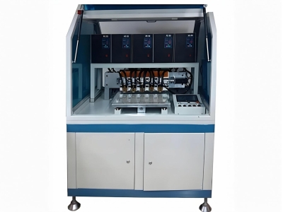
Ferrite and patch placement determines how much flux reaches the coil before the module is implanted. Equipment: Auto Patch Pick and Place Machine.
Design Rules That Survive Production
✓ Cover the plate, not the card
Ferrite is needed where the metal is, with a margin of one to two millimetres around the plate. Covering the entire card body adds cost and stiffness without adding flux.
✓ Stack when thickness is capped
If the cavity depth limits you to 0.10 mm, two bonded 0.10 mm layers usually outperform one 0.20 mm layer of the same material, because the bond line interrupts eddy paths in the sheet itself.
✓ Respect the bridge geometry
The two connection bridges crossing the coil are part of the antenna. If ferrite stops short of the bridges, the field sees an asymmetric load and the card reads directionally, working on one face and failing on the other.
✓ Protect the ferrite from mechanical abuse
Flexible ferrite cracks. A cracked sheet still looks installed but stops shielding locally. Specify a protective cover layer and include a bend test in the qualification, not only an electrical one.
Reference Values for a Dual-Interface Stack
Typical reference values only. Ferrite selection must be confirmed against the actual module footprint, cavity depth and card body material, since all three change the magnetic path.
Where the Ferrite Decision Matters Most
The same reasoning applies wherever a metal body sits close to an inductively coupled coil:
- Dual-interface banking and government cards with ISO 7816 contact plates
- Mobile payment SIM and embedded secure element packages with metal frames
- Wearable payment devices where the antenna runs under a metal bezel
- Access cards with metal reinforcement or metal mounting plates
- Any hybrid card where contactless performance is specified but the module is chosen for contact reasons
Frequently Asked Questions
Can I solve a weak contactless interface by adding antenna turns?
Not usually. Extra turns raise inductance, which detunes the coil away from 13.56 MHz and raises series resistance, so Q falls. The ferrite addresses a shielding problem: flux that never reaches the coil. Adding turns addresses a coupling problem that does not exist yet.
Is ferrite always required on a dual-interface card?
It is required whenever the contact plate is large relative to the coil and the module sits within a few tenths of a millimetre of the turns, which describes most dual-interface cards. Very small modules with generous keep-out can work without it, but transaction distance will be shorter and far more sensitive to reader antenna design.
Does the ferrite change how the contact interface behaves?
Electrically, no: the sheet is an insulator and the ISO 7816 pads are unaffected. Mechanically, yes: it adds stack height and stiffness, so cavity depth, module seating force and peel strength all need to be re-verified after the change.
Next Step
More equipment in this range is listed on the ZOWINDA CardMachine product page, and related application notes appear in our Industry News section.
Related reading:
- Printed Antenna Tolerance: Which Dimension Actually Moves Resonance
- Isotropic Conductive Adhesive Cure: The Three-Variable Window Behind Module Opens
- Auto Patch Pick and Place Machine for Smart Card Production
- Contactless Card Test Programme: One Matrix for Electrical, Mechanical and Functional
Ready to boost your production efficiency?
Contact us for a tailored solution and quotation on inlay production, card testing and personalisation equipment.
Email: info@zowinda.com
WhatsApp: +86 186 2085 0485
 Isotropic Conductive Adhesive
 Dual-Interface Ferrite: Why Sh
 Printed Antenna Tolerance: Whi
 Contactless Card Test Programm
Please contact us with your request
We are ready to answer your questions.