
Contactless Card Read Range: Diagnosing Antenna Resonance and Detuning
Smart Card Manufacturing Notes
Contactless Card Read Range: Diagnosing Antenna Resonance and Detuning
Published: November 12, 2026 | ZOWINDA Application Engineering
When a finished card reads at four centimetres instead of the ten the specification promised, the instinct is to blame the chip. The chip is almost never the problem. A contactless card is a resonant circuit that has to be tuned to a reader field, and the moment the inlay is laminated into a card body, personalised, and handed to a customer with a wallet full of other cards, that tuning moves. Read range is the visible symptom of a resonance that no longer sits where the reader expects it, and it is diagnosable long before a customer complains.
Three Numbers Decide Whether a Card Reads
The first number is resonance frequency. An inlay is designed to resonate at 13.56 MHz, but no inlay is measured naked. Bare inlay resonance is normally set deliberately high, in the mid teens of megahertz, because lamination adds dielectric material around the coil and the printed conductor sits closer to a metal-free but still lossy body; both effects pull resonance down. A card whose post-lamination resonance lands at the reader frequency is a card that was designed with that shift in mind. A card whose resonance lands low reads weakly and only close to the reader, because the reader field is driving a circuit that is no longer resonant with it.
The second number is Q, or more usefully bandwidth. High Q gives a narrow, efficient resonance: good range at exactly the right frequency, poor tolerance of anything that shifts the frequency. Payment and transit cards therefore run deliberately damped, which trades a little peak range for a resonance broad enough to survive a body, a module and a wallet. The symptom of over-damping is a card that reads at any distance but never far; the symptom of under-damping is a card that reads brilliantly in isolation and fails next to a phone.
The third number is the field strength at which the card starts to work. Standards describe a minimum operating field and a reference plane for measuring it, and a card that only starts at twice that field is a card that will fail on the weaker readers in the installed base, even though it passes on the bench. These three numbers, resonance position, bandwidth and starting field, explain nearly every read range complaint that is not a mechanical or a cryptographic failure.
A Diagnostic Sequence That Finds the Cause
- Measure the bare inlay first. Record resonance and Q before lamination. If the inlay is already out of its own window, nothing downstream can be diagnosed and the antenna print or etch is the suspect.
- Measure again after lamination. The shift from bare inlay to finished card is the single most informative number in the whole exercise. Compare it against the shift your design assumed; a body material change is the usual reason this number moves.
- Measure after module implanting and personalisation. A module adds metal and a cavity adds an air gap. Both perturb the field around the coil. Measuring at each step localises the drift to a process rather than to a design.
- Test at the standard reference plane. Bench range measured in free air flatters every card. Use a calibrated reference reader and the specified test positions, so the number you report is comparable with the scheme requirement.
- Test in the presence of neighbours. Stack several cards, or place the card on a phone, and watch the starting field rise. A card that only passes alone has no margin, and margin is what field reliability is made of.
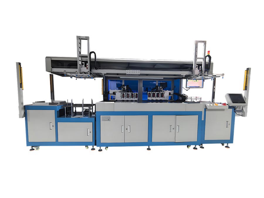
Figure: swept-frequency measurement of card resonance, the fastest way to see a detuning problem before it reaches a customer. Equipment: Automatic Frequency Test Machine.
What Actually Moves the Tuning
✓ Body Dielectric and Thickness
Every plastic between the coil and the reader adds capacitance and loss. A thicker or higher-permittivity body pulls resonance down and widens bandwidth, which is why a material change is a retuning event, not a purchasing decision.
✓ Metal Anywhere Nearby
A module, a metal inlay carrier, a foil pouch or a phone back all absorb field energy. The card does not have to touch the metal: proximity is enough to shift resonance and collapse range.
✓ Antenna Geometry and Print Tolerance
Coil inductance scales with turns and area. A print process that varies track width or dielectric thickness between antenna and bridge changes inductance run to run, so the resonance distribution is a process capability question.
✓ Chip Input Capacitance
The chip is part of the resonant tank. Substituting a chip with different input capacitance without recalculating the antenna is one of the most common causes of a silent yield drop after a component change.
Reference Values for Diagnosis
Figures above are reference points for diagnosis, not a card specification. Acceptable windows come from the payment scheme or application standard you are qualified against, and must be confirmed on your own body and chip combination.
Where This Pays for Itself
The economics are simple. A detuning problem discovered at the inlay reel costs a reel. The same problem discovered after lamination costs the sheets, the modules and the personalisation run, and if it is discovered by a customer it costs the relationship as well. A frequency measurement takes seconds per card, and it converts an argument about whose fault a range complaint is into a trend line that names the process responsible. Read together with the inlay sheet yield note and the test programme note, this is the first of three measurements that decide whether a contactless card works in the field.
- Incoming inspection of inlay reels, before lamination commits the material
- Qualification of a new card body material or thickness
- Root-causing a read range complaint that appears only in the field
- Line-side sampling after a chip or antenna supplier change
Frequently Asked Questions
Can read range be increased just by adding turns to the antenna?
Not reliably. Adding turns raises inductance and lowers resonance, and it also raises the parasitic capacitance that flattens Q. The usual result is a card that is louder on the bench and no better at the reference plane. Range improves when the tank is tuned for the body it actually lives in.
Why does a card work on one reader and fail on another?
Readers differ in antenna geometry, field strength and modulation depth. A card running close to the minimum field will pass on a strong reader and fail on a compliant but weaker one. That is a margin problem, and margin is set by resonance and damping, not by the reader you happened to test on.
Does a metal card body rule out contactless operation?
It rules out a plain antenna. Metal shifts resonance severely and absorbs field, so metal-bodied cards need a ferrite layer and a retuned coil, and their range is still shorter than a plastic card of the same size. It is a different design, not a tweak.
Next Step
More equipment in this range is listed on the ZOWINDA CardMachine product page, and related application notes appear in our Industry News section.
Related reading:
- Inlay Sheet Yield Maths: Where a Two Percent Layout Change Pays
- Contactless Card Test Programme: One Matrix for Electrical, Mechanical and Functional
- Automatic Frequency Test Machine for RFID and NFC Cards
- High-Speed RFID Card Production Inlay Sheet Manufacturing Line
- Automatic IC Module Testing Machine for Smart Card Production
Ready to boost your production efficiency?
Contact us for a tailored solution and quotation on inlay production, card testing and personalisation equipment.
Email: info@zowinda.com
WhatsApp: +86 186 2085 0485
 Contactless Card Test Programm
 Inlay Sheet Yield Maths: Where
 Contactless Card Read Range: D
 Automated Card Sealing, Labeli
Please contact us with your request
We are ready to answer your questions.