
Auto Patch Pick and Place Machine Guide 2026 | Zowinda
Auto Patch Pick and Place Machine Guide 2026 | Zowinda
Smart card and RFID inlay manufacturers face a persistent bottleneck between manual bonding and fully automated production lines: placing RFID inlays, chip modules, and adhesive patches onto card sheets with consistent accuracy. The Zowinda Auto Patch Pick and Place Machine closes that gap. This 2026 guide explains what the equipment does, why placement accuracy drives yield, how the machine operates on the factory floor, and which specifications matter when you evaluate a patch pick and place machine for your line.
Whether you produce contactless payment cards, dual-interface ID cards, transit tickets, or RFID labels, precise RFID inlay placement is the difference between a readable card and a scrap sheet. Below we break down the process, the technology, and the business case.
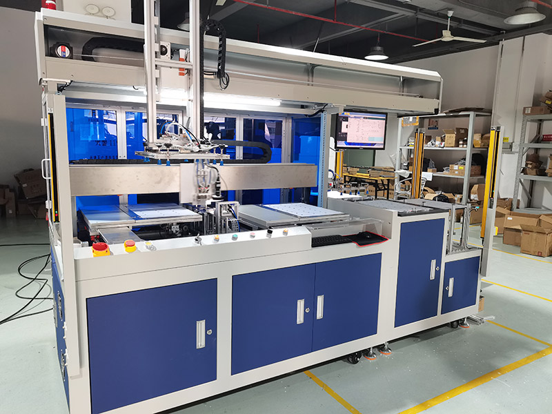
What Is an Auto Patch Pick and Place Machine
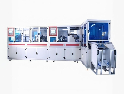
A patch pick and place machine is a vision-guided robotic station that picks individual components — RFID wet or dry inlays, chip modules, PCB antennas, or pre-laminated adhesive patches — and places them onto card sheets, modules, or inlay substrates at a fixed position and orientation. It sits between manual bonding (slow, inconsistent) and a fully integrated inlay line (high capital cost), giving mid-volume manufacturers production-scale accuracy without a full-line investment.
In smart card production, the machine typically receives a printed or milled inlay sheet, identifies the target location using a CCD camera, and deposits the patch with sub-millimeter repeatability. The result is a sheet ready for lamination or further embedding, with every component verified before it moves downstream.
Why Precise Patch Placement Matters in Smart Card Production
Patch position directly affects two things customers care about: read performance and yield. If an RFID inlay is shifted by even a millimeter, the antenna coupling changes and the card may fail a read test at the point of sale. If a chip module is misaligned, the subsequent lamination or milling step can damage the die, creating scrap.
For dual-interface cards, the patch must align with the cavity milled earlier in the process. Tight placement tolerance keeps the contact module centered over the cavity, protecting the bond and the electrical contact. Consistent smart card component placement also reduces rejection rates at final testing, which is where most hidden cost lives.
- Read reliability: Correct antenna position preserves coupling margin for contactless and NFC cards.
- Lower scrap: Fewer misplaced patches means fewer sheets rejected at lamination or test.
- Process compatibility: Aligned patches fit downstream milling, embedding, and lamination tooling without adjustment.
- Brand consistency: Uniform placement produces a premium finished card appearance.
How the Zowinda Patch Pick and Place Machine Works
The workflow is built around a CCD vision system and a multi-head placement gantry. The sequence runs as follows:
- Sheet loading: An automatic feeder presents the inlay sheet or module, with anti-stick and anti-double-sheet detection to avoid misfeeds.
- Vision registration: The CCD camera reads fiducials or sheet edges and calculates the offset and rotation of the substrate.
- Pick: Vacuum nozzles pick the inlay, chip, or patch from the component feeder or reel.
- Place: The gantry deposits the component at the corrected coordinates with +/-0.1 mm accuracy.
- Verify and reject: A reject station removes any sheet with a missing or misplaced component before it advances.
Recipe management stores coordinates and component types per card layout, so switching between products takes minutes instead of hours. This is what makes a automatic pick and place cell practical for contract manufacturers that run many short jobs.
Key Features and Production Benefits
- Vision-guided alignment: Sub-millimeter positioning accuracy driven by a CCD system with +/-5 micron repeatability.
- Multi-head throughput: Simultaneous pick-and-place reaches 3,000 to 4,500 units per hour depending on the model and component.
- Broad component support: Handles RFID wet inlays, dry inlays, PCB antennas, and pre-laminated adhesive patches.
- Automatic feeding: Anti-stick and anti-double-sheet detection keeps the line running without operator intervention.
- Fast changeover: Recipe library stores layouts and patch types for quick job switching.
- Integrated reject: Misplaced or missing components are separated automatically, protecting downstream yield.
From an operations standpoint, the cell is designed for low attention. Routine maintenance is limited to nozzle cleaning, feeder inspection, and periodic calibration of the vision system. Because placement is recipe-driven, new operators reach stable output quickly after training, and production managers get predictable cycle times for planning.
Technical Specifications
| Parameter | Specification |
|---|---|
| Placement Accuracy | +/-0.1 mm |
| Throughput | 3,000 - 4,500 units/hour (model dependent) |
| Substrate Size | CR80 / ISO 7810 card, max 110 x 80 mm |
| Component Types | RFID inlay, chip module, adhesive patch |
| Vision System | CCD camera, +/-5 micron repeatability |
| Power Supply | AC 220V / 50-60 Hz |
| Air Supply | 0.5 - 0.7 MPa clean dry air |
| Machine Weight | approx. 480 kg |
Quality Workflow and Yield Improvement
The biggest hidden cost in card production is rejection at final test. A patch pick and place machine attacks that cost at the source: by placing every component within tolerance and verifying each placement before the sheet advances, it prevents the misalignment that later becomes scrap. Combined with inline electrical testing on the inlay line and a spot pressure test after lamination, manufacturers can drive placement-related rejects toward zero.
For contract manufacturers, the recipe system also supports traceability. Each job stores its placement coordinates and component type, so a quality claim can be traced back to the exact settings used. That documentation matters for banking, telecom, and government card programs.
Application Scenarios by Industry
Because the machine handles a wide range of patch types, it serves several distinct markets. Understanding the application helps you specify the right feeder, nozzle, and throughput configuration.
Contactless Payment and Banking Cards
Payment cards require a precisely placed dual-interface module and, in many designs, an embedded antenna patch. Tight placement keeps the module centered over the milled cavity and preserves the antenna coupling needed for tap-to-pay performance.
Transit and Access Control Cards
Transit agencies and office access systems issue millions of RFID cards. High throughput and consistent placement let bureaus meet volume targets while keeping rejection rates low across long production runs.
Government ID and E-Document Cards
National ID, e-passport pre-laminate, and health card programs demand traceability and near-zero defect rates. Recipe-based placement and inline verification provide the documentation these programs require.
RFID Labels and Tags
Beyond cards, the same placement principle applies to RFID label embedding and sample bonding workflows where accurate patch positioning directly impacts read distance and yield.
Integration Into a Complete Smart Card Line
The patch pick and place cell is rarely the only machine on the floor. In a typical contactless card flow it sits after sheet printing or cavity milling and before lamination. Upstream, an Auto Contactless Card Inlay Line builds the antenna sheet; the patch machine then adds the chip module or secondary patch. After lamination, a Spot Pressure Tester confirms bond strength and a Frequency Test Machine confirms antenna performance.
Designing the cell with standard CR80 and ISO 7810 substrates in mind, plus a max format of 110 x 80 mm, lets it drop into most existing layouts without rework. The PLC and HMI control architecture also matches the rest of the Zowinda equipment family, so operators trained on one machine transfer easily to another.
Related Zowinda Smart Card Production Equipment
The patch pick and place cell works best as part of an integrated line. Explore these related Zowinda machines:
- Auto Contactless Card Inlay Line - the upstream line that builds RFID/NFC inlay sheets before patch placement.
- ICC Backside Spot Pressure Tester - verifies chip bond strength after lamination.
- RFID NFC Card Frequency Test Machine - confirms antenna performance on finished cards.
Frequently Asked Questions
What components can the patch pick and place machine handle?
It is compatible with RFID wet inlays, dry inlays, PCB antennas, chip modules, and pre-laminated adhesive patches. The feeder and nozzle configuration can be adjusted per component type through the recipe system.
What placement accuracy can I expect?
The machine achieves +/-0.1 mm placement accuracy, supported by a CCD vision system with +/-5 micron repeatability. Real-world accuracy depends on sheet flatness and feeder setup, but production results stay well within smart card tolerances.
How fast is the throughput?
Throughput ranges from 3,000 to 4,500 units per hour depending on the model and component complexity. Multi-head configurations place several components in parallel to reach the upper end of that range.
Can it handle different card layouts?
Yes. Recipe management stores coordinates and component types for each layout, and changeover between jobs takes only minutes. This makes the cell suitable for both dedicated production and contract manufacturing with many short runs.
Does Zowinda provide installation and training?
Yes. Zowinda provides installation, commissioning, operator training, and technical documentation. Remote support is available for software and process troubleshooting, and spare parts are stocked for fast delivery.
Get a Quote for Your Patch Placement Line
If you are building or upgrading a smart card or RFID inlay production line, Zowinda can help you select the right automatic pick and place configuration for your component mix, substrate size, and throughput targets.
Contact us to request a customized quote and technical consultation:
Email: [email protected]
WhatsApp: +86 186 2085 0485
 Full Auto Milling & Implan
 Non-Standard Contactless Card
 Smart Card Inspection System -
 Revolutionizing Card Productio
Please contact us with your request
We are ready to answer your questions.