
Laser Marking on Card Faces: Contrast, Depth and Surface Integrity
Smart Card Manufacturing Notes
Laser Marking on Card Faces: Contrast, Depth and Surface Integrity
Published: November 18, 2026 | ZOWINDA Application Engineering
Laser marking is usually filed under personalisation software, next to the fonts and the data layout. Physically it is a materials process: the beam does not put anything on the card, it changes what is already there, and the mechanism it uses, whether carbonisation, foaming or removal of a top layer, decides both how the mark looks and how the card behaves for the next five years. Two cards can carry the same data in marks that measure the same contrast and have completely different durability, because the depth and the mechanism were different.
Three Mechanisms, Three Consequences
On PVC the beam decomposes the polymer and leaves a carbonised, yellow-brown to dark mark. The process is chemically dirty: PVC is more than half chlorine by weight, and the beam releases hydrogen chloride along with the tars that make the mark visible. The mark is brittle relative to the surrounding material, and it darkens further with heat and time. Contrast is moderate, which is why PVC marking tends to look grey rather than black, and it is achieved by going deeper, which is exactly the wrong trade on a card that will be flexed.
On polycarbonate and on PET-G with the right additive package the mechanism is foaming rather than burning. The beam vaporises a dispersed phase or a small amount of absorbed moisture and the resulting gas bubbles scatter light, producing a white or light grey mark on a coloured body. The contrast is high, the edges are clean, and the mark requires no pigment. Mechanically, though, a foamed region is a region of reduced density and reduced strength, and the bubble structure is a place where a bend will start a crack if the mark is wide and deep and sits in the bending zone.
The third mechanism is ablation: a dark cap layer, a printed panel or a thin coating is removed to expose a lighter body underneath. This produces the highest contrast of the three and it also removes the abrasion protection that the cap layer provided. A card whose mark is ablation-based will look excellent on the perso line and progressively lose contrast in a wallet, not because the mark faded but because the unprotected area around it wore and dirt collected in the ablated recess.
Whatever the mechanism, depth is a structural variable. Marking that stays inside the overlay consumes decoration and leaves the body core intact. Marking that penetrates into the core removes load-bearing material, creates a notch on the tensile face, and in a three-layer body creates a path where moisture and plasticiser can move. There is no universal depth, but there is a universal limit: depth should stay a small fraction of body thickness, typically well under a quarter, and the mark should never reach the antenna layer on the same face.
Qualifying a Mark Recipe as a Process
- Choose the mechanism deliberately, from the body material. Decide whether the card will be marked by carbonisation, foaming or ablation before artwork is fixed. A design that expects black text on a polycarbonate body is asking for carbonisation on a material that prefers foaming, and the result will be either weak contrast or excessive depth.
- Measure contrast objectively on production cards. Define illumination, aperture and the greyscale or reflectance difference between mark and background, then measure cards from each shift rather than judging by eye. Human assessment accepts a range of about two to one in perceived contrast, which is far too wide for a controlled process.
- Set a depth limit tied to thickness and to the antenna keep-out. Verify the depth by cross-section at recipe setup, then confirm it on periodic audits. Write the keep-out as a distance from the module and from the antenna footprint, so that a layout change cannot quietly move a mark into a sensitive area.
- Qualify durability as a sequence, not as a single test. Run surface abrasion first, then bending and torsion, then re-read the card electrically. A mark that survives abrasion but cracks under bending, or a mark that looks intact while the antenna underneath has been cut, only reveals itself when the tests are chained in service order.
- Keep the beam recipe under the same change control as the data file. Power, frequency, speed, focal offset and pass count are product parameters. A change to any of them is a product change and needs a first-article check of contrast, depth and card readability before release.

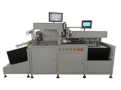
Laser marking is a controlled material change: depth decides durability as much as contrast does. Equipment: Sheet Cutting and Laser Engraving System for Card Production.
Rules That Protect the Surface After Marking
✓ The overlay is protection you have already paid for
Marking inside the overlay keeps that protection. Ablating through it buys contrast with durability, which is a fair trade only for cards that are never handled hard.
✓ Respect the module keep-out
Heat and local stress near the module reach the adhesive joint and the chip. Keep marking a defined distance from the module edge, and never mark over the contact plate on a dual-interface card.
✓ Sequence marking before final verification
Marking is irreversible. Place it before the last electrical and visual verification so that a card with a rejected mark is rejected at the line rather than after it has been packed and shipped.
✓ Watch focal variation across the sheet
Beam focus depends on the distance to the surface, and a sheet that is not flat produces marks of different depth across the field. Flatness and clamping are part of the marking process, not part of the fixture.
Reference Values for Card Face Marking
Typical reference bands for 0.76 to 0.84 millimetre PVC, PET-G and polycarbonate cards marked on a personalisation line. Contrast targets, depth limits and keep-out distances depend on body construction, overlay type and the applicable card standard, and must be confirmed on your own cards with your own reader and test equipment.
Where Marking Quality Decides the Product
The marking recipe matters most where the marked area is large, is handled constantly, or sits close to the electronics:
- Payment and transit cards with laser-marked card numbers and expiry dates
- ID and access cards marked with photographs, serial numbers and barcodes
- SIM and payment module cards marked on a small, high-contrast area near the chip
- Personalised membership and loyalty cards with variable data and panels
- Dual-interface cards where the marking area is defined by the contact plate layout
Frequently Asked Questions
Can a bad laser mark be removed or re-marked?
No. The mark is a change in the material, so there is nothing to erase. A rejected mark means a rejected card, which is why marking is normally sequenced before the final verification step and why the recipe is locked down as a product parameter.
Why does contrast vary across a single sheet?
Focus distance changes with sheet flatness, and beam energy delivery changes with spot size and speed. If the sheet is not held flat, cards near the centre and near the edge receive different energy densities. Flatness and clamping belong in the process specification.
Does laser marking damage the antenna?
Not if the depth stays inside the overlay and the mark respects the keep-out. If a mark penetrates to the antenna layer it can cut a turn, change the conductor width and shift resonance, or create a path for moisture that later shows up as a corrosion failure. Both are measured the same way: mark, then test frequency and read range.
Next Step
More equipment in this range is listed on the ZOWINDA CardMachine product page, and related application notes appear in our Industry News section.
Related reading:
- Card Face Printing and Read Range: Where Ink and Overlay Sit in the Stack
- Inlay-to-Body Registration: The Tolerance Chain Behind a Working Card
- Key Injection and Audit Trail: The Part of Personalisation That Gets Audited
- Dual-Interface Bridge: Making the Contact and Contactless Paths Agree
- GSM Card Personalization Machine P8600 - SIM Card Data Encoding and Printing
Ready to boost your production efficiency?
Contact us for a tailored solution and quotation on inlay production, card testing and personalisation equipment.
Email: info@zowinda.com
WhatsApp: +86 186 2085 0485
 Laser Marking on Card Faces: C
 Inlay-to-Body Registration: Th
 Card Face Printing and Read Ra
 Key Injection and Audit Trail:
Please contact us with your request
We are ready to answer your questions.