
High-Speed RFID Card Production Inlay Sheet Manufacturing Line
High-Speed RFID Card Production Inlay Sheet Manufacturing Line: Engineering Notes from the Production Floor
Published: November 05, 2026 | ZOWINDA Application Engineering
An inlay sheet is where a contactless card is actually made. Antenna wire is embedded into a core sheet at a fixed pitch, overlay sheets are laminated above and below, and the panel that comes out already carries its final resonance, its final thickness and its final mechanical strength. Everything downstream - patch placement, cavity milling, personalization - can only preserve or destroy what the inlay line decided. That is why a high-speed inlay line is judged on two numbers at once: sheets per hour, and the spread of electrical parameters across a single sheet.
What the Line Actually Does
The line is a sequence of stations sharing one registration system. A core sheet of PVC, PET or PC is fed and referenced against a datum; antenna wire is embedded by an ultrasonic or thermal head that lays it in a programmed path and stakes it into the sheet; an interconnect station may bond a strap or a chip position onto the antenna ends; overlay sheets are added and the stack enters a lamination press that applies pressure, temperature and dwell under vacuum. After cooling the panel is flattened, measured and released to the next operation.
Two physical relationships dominate the process. The first is inductance: the number of turns and the pitch between them set it, so a wire that wanders by a fraction of a millimetre moves the resonant frequency of every card cut from that sheet. The second is the dielectric: lamination pressure and temperature decide how much air remains between the layers, and air changes the effective permittivity the antenna works against. Neither effect is visible in a card that is only read functionally, and both are permanent once the sheet is cured.
Production Sequence
- Sheet feed and registration. The core sheet is squared to the machine datum. A sheet that wanders by half a millimetre moves every antenna pattern printed on it by the same amount.
- Antenna embedding. Wire is laid in a programmed path at closed-loop tension and staked to a controlled depth. Turn pitch accuracy is inductance accuracy, and this is the station where it is won or lost.
- Interconnect. Where the product needs a strap or a direct chip position, the antenna ends are bonded and the joint is checked before lamination locks it permanently under overlay film.
- Overlay lamination. The stack is pressed under vacuum with programmed pressure, temperature and dwell, which together set final thickness, void content and the dielectric the antenna sees.
- Cooling, flattening and inspection. The panel is stabilised, flattened and checked for dimensional and electrical conformity before release to trimming and patch placement.

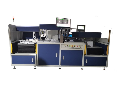
Figure: inlay sheet manufacturing line combining antenna embedding, overlay lamination and sheet handling. Equipment: High-Speed RFID Card Production Inlay Sheet Manufacturing Line.
Key Advantages
✓ One Registration System
Feeding, embedding and lamination share a datum, so antenna position on the sheet is one controlled value rather than the sum of three independent tolerances.
✓ Tension-Controlled Embedding
Wire tension and stake depth run closed-loop. A loose turn or a wire pressed too deep both surface later as frequency spread, and neither can be corrected after lamination.
✓ Recipe-Driven Lamination
Pressure, temperature, dwell and vacuum are stored per product, so moving from PVC to PET-G is a recipe change rather than a press re-tuning exercise.
✓ Traceability by Sheet
Process parameters and inspection results are recorded per sheet, which is what makes a customer claim traceable to a shift instead of to a memory.
Technical Data
Layouts, wire diameter, antenna geometry and lamination parameters are set from your card specification and from the standard your product is certified against. ZOWINDA configures tooling and recipes against the antenna design you supply.
Where the Line Pays Back
The decision to run inlays in-house is a supply question before it is a cost question. Bought-in sheets arrive with someone else process window already baked in, and a change in their lamination pressure surfaces in your personalization yield weeks later with no visible cause. Owning the line puts that variable inside your own SPC. The second case is design iteration: a new antenna geometry, a thinner core or a different overlay film can be trialled on a few sheets instead of ordering a production lot, which shortens the loop between an RF simulation and a card that can actually be measured.
- Bringing inlay production in-house instead of buying sheets
- Capacity expansion where sheet supply is the bottleneck
- Second-source qualification of a laminate or wire supplier
- Pilot builds for a new antenna design before tooling commitment
Frequently Asked Questions
Wire embedding or etched aluminium - which route should we run?
Wire embedding is the mainstream route for HF and NFC inlays because copper wire gives lower resistance per turn and the geometry changes by reprogramming rather than by etching a new artwork. Etched aluminium stays attractive at very high volume and in thin constructions. The line is configured for one route, so tell ZOWINDA which one your design assumes.
Can one line run several sheet layouts?
Yes - layout is a tooling and recipe question. Multi-up arrangement, sheet outline and antenna path are stored per product, and changeover is a tooling swap with the matching recipe selection. What does not change is the registration philosophy, which is why sheets from different layouts stay comparable.
How do we know resonance is right before the sheet is cut?
Sampling is the practical answer. Units cut from corners and centre are measured for resonance and Q, and the spread across the sheet tells you whether embedding tension or lamination pressure has drifted. Full-card measurement belongs at the next station, after cutting and patching.
Next Step
More equipment in this range is listed on the ZOWINDA CardMachine product page, and related application notes appear in our Industry News section.
Related reading:
- Integrated Inlay Manufacturing System
- Integrated Chip Placement and Wire Embedding/Welding System
- Automatic IC Module Implanting Machine
Ready to boost your production efficiency?
Contact us for a tailored solution and quotation on the High-Speed RFID Card Production Inlay Sheet Manufacturing Line.
Email: info@zowinda.com
WhatsApp: +86 186 2085 0485
 Auto Patch Pick and Place Mach
 Auto Sheet Trimming Machine fo
 High-Speed RFID Card Productio
 Automatic IC Module Testing Ma
Please contact us with your request
We are ready to answer your questions.