
Integrated Inlay Manufacturing System | All-in-One RFID Inlay Production Equipment
Integrated Inlay Manufacturing System: Engineering Notes from the Production Floor
Published: November 02, 2026 | ZOWINDA Application Engineering
An RFID inlay is only as reliable as the interfaces between its antenna, its chip and its substrate. An integrated inlay manufacturing system keeps those three processes under one control architecture, so registration, wire tension and lamination profile stay coherent from the first antenna loop to the finished sheet.
Why an Integrated Line Beats Stitching Separate Machines Together
Running wire embedding, chip placement and lamination on separate machines is common at low volume, but every transfer between machines introduces its own registration error, its own operator judgement and its own queue. When the steps share one platform, the sheet never leaves the same reference frame: the antenna coordinates recorded by the embedding head become the coordinate system that the placement head and the laminator inherit.
The benefit shows up in yield. Inlay scrap clusters at interfaces - an antenna that drifted, a chip bonded to a pad that had already been re-registered, a lamination window that opened before the adhesive reached activation temperature. Consolidating the process removes most of those interfaces, and the ones that remain become measurable rather than accidental.
How the Line Runs
- Substrate feed and tension control. PET, PVC or PC substrate is unwound under closed-loop servo tension, so the antenna pattern is embedded into a dimensionally stable web.
- Wire embedding and antenna forming. Ultrasonic or thermal embedding seats the antenna wire to a programmed layout; the actual position is logged as the reference for the next station.
- Chip placement and bonding. The placement head picks the die, aligns it to the inherited antenna coordinates and bonds it with anisotropic adhesive or ACP.
- Lamination and singulation. Cover sheets are laminated at a controlled temperature and pressure curve, then the sheet or roll is cut to the format the personalization line expects.
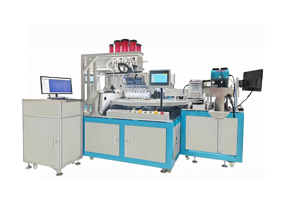
Figure: integrated wire embedding, chip placement and lamination on a single platform. Equipment: Integrated Inlay Manufacturing System.
Key Advantages
✓ One Reference Frame
Registration captured at embedding is inherited by placement and lamination, removing per-station re-homing and the drift it causes.
✓ Closed-Loop Tension
Servo tension control holds the substrate stable at line speed, which prevents antenna stretch and the read-range loss that follows it.
✓ In-Process Verification
Optical and electrical checks flag missing or displaced chips before lamination, so defects are repaired at the cheapest possible point.
✓ Recipe-Driven Changeover
Product recipes store wire layout, bond profile and lamination curve together, which brings changeover down to minutes instead of shifts.
Technical Data
Values describe the standard configuration. Final figures depend on substrate, chip type and requested throughput; ask ZOWINDA for a line layout based on your product mix.
Where It Fits in Production
The system suits manufacturers moving from pilot volumes to series production, and operations that already run separate stations but lose yield at the handovers. Because the platform is modular, a line can start with embedding and add placement or lamination later without rebuilding the material handling.
- Contactless payment and transit inlay sheets
- NFC tag and label converting lines
- Dual-interface and loyalty card inlays
- UHF retail and logistics label inlays
Frequently Asked Questions
What throughput should we plan for?
Throughput depends on antenna complexity and chip pitch. Share your inlay layout and annual volume and ZOWINDA will size the stations so that the slowest one does not throttle the line.
Can the line run only part of the process?
Yes. The stations are modular, so a buyer can begin with wire embedding and add placement and lamination as volume grows.
How is chip placement accuracy held after lamination?
Because the placement head works from the antenna coordinates recorded at embedding rather than from a re-homed datum, post-lamination shift is limited to the dimensional behaviour of the substrate itself.
Next Step
More equipment in this range is listed on the ZOWINDA CardMachine product page, and related application notes appear in our Industry News section.
Ready to boost your production efficiency?
Contact us for a tailored solution and quotation on the Integrated Inlay Manufacturing System.
Email: info@zowinda.com
WhatsApp: +86 186 2085 0485
 Smart Card Cavity Milling Mach
 Automatic IC Module Implanting
 Integrated Inlay Manufacturing
 Intelligent Envelope Sorting S
Please contact us with your request
We are ready to answer your questions.