
Integrated Chip Placement and Wire Embedding/Welding System
Integrated Chip Placement and Wire Embedding/Welding System: Engineering Notes from the Production Floor
Published: November 03, 2026 | ZOWINDA Application Engineering
Two processes decide whether an RFID inlay works: the antenna has to sit where the design says it sits, and the chip has to land exactly on the antenna pads. When embedding and placement run on separate machines, every transfer adds a registration error that the next station inherits. An integrated system closes that loop - the welding head logs where each antenna actually is, and the placement head bonds the die to those measured coordinates.
Why Integration Changes the Registration Problem
In a two-machine line, the embedding machine positions the antenna against its own datum, the sheet is then moved, re-gripped and re-referenced on the placer, and each of those steps contributes tolerance. A sheet that flexes between stations, or a gripper that seats a millimetre off, shows up later as a chip that straddles the antenna pad and reads with a shortened range - or not at all.
With both heads on one frame, the coordinate system is shared. The welding station records the as-built antenna position per sheet, the vision system on the placement head aligns the die against that record rather than a nominal layout, and the two stations can be takt-balanced in one controller instead of negotiated between two.
How the Two Stations Cooperate
- Wire embedding. The embedding head seats antenna wire into the substrate at programmed coordinates and logs the as-built layout for the sheet.
- Welding and termination. Antenna wire terminations are welded at controlled energy, so joint resistance stays consistent across the sheet.
- Vision hand-off. The placement camera reads the logged coordinates plus live marks, compensating for substrate drift before the die is picked.
- Chip bonding. The die is placed and bonded with anisotropic adhesive or ACP, aligned to the measured antenna rather than the nominal design.
- Verification and release. Electrical and optical checks confirm each bond before the sheet moves on, and rejects are flagged with position data.
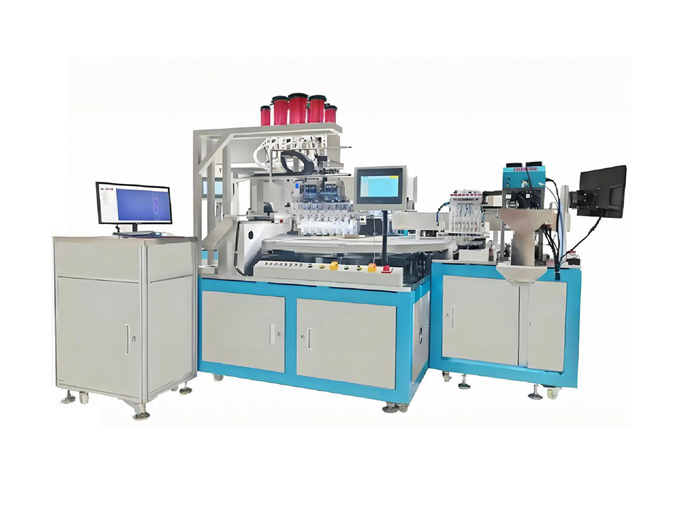
Figure: chip placement and wire embedding/welding heads working from one shared reference frame. Equipment: Integrated Chip Placement and Wire Embedding/Welding System.
Key Advantages
✓ Shared Datum
Placement works from the antenna coordinates recorded at welding, removing re-grip and re-homing errors between machines.
✓ Consistent Weld Joints
Energy-controlled welding keeps termination resistance stable, which protects final read range and yield.
✓ Takt Balancing
Both stations report to one controller, so cycle time is balanced across the pair instead of idling whichever station is slower.
✓ Traceable Rejects
Each rejected bond carries its sheet and position record, so process drift is caught as a trend, not as end-of-line scrap.
Technical Data
Values describe the standard configuration and are typical, not guaranteed. Final figures depend on antenna layout, chip type and requested throughput; ZOWINDA confirms them against your inlay design.
Where It Fits
The system suits manufacturers who currently run embedding and placement apart and lose single-digit yield at the handover, and new lines that want one supplier responsible for the whole antenna-to-die chain. Because the stations share one control platform, a buyer can qualify the line with one recipe set and scale throughput by adding parallel frames rather than re-engineering the process.
- HF and UHF RFID inlay production
- NFC tag and label manufacturing
- Transit and payment inlay lines
- Retrofitting an existing embedding line with integrated placement
Frequently Asked Questions
Can it handle different antenna designs on one line?
Yes. Antenna layout, weld energy and die placement are stored as product recipes, so changeover between designs is a selection, not a re-teach.
What accuracy should we expect at the chip joint?
Placement aligns to the measured antenna coordinates, so accuracy at the joint is dominated by the vision system and bonding process rather than by accumulated machine-to-machine tolerance. ZOWINDA validates the figure on your actual inlay during acceptance.
Does one operator run both stations?
Typically yes. The integrated HMI supervises embedding, welding and placement, with alarms and recipes in one place.
Next Step
More equipment in this range is listed on the ZOWINDA CardMachine product page, and related application notes appear in our Industry News section.
Ready to boost your production efficiency?
Contact us for a tailored solution and quotation on the Integrated Chip Placement and Wire Embedding/Welding System.
Email: info@zowinda.com
WhatsApp: +86 186 2085 0485
 Auto Wire Embedding Machine (2
 ICC Backside Spot Pressure Tes
 Integrated Chip Placement and
 Smart Card Cavity Milling Mach
Please contact us with your request
We are ready to answer your questions.