
Isotropic Conductive Adhesive Cure: The Three-Variable Window Behind Module Opens
Smart Card Manufacturing Notes
Isotropic Conductive Adhesive Cure: The Three-Variable Window Behind Module Opens
Published: November 13, 2026 | ZOWINDA Application Engineering
A module that reads open on a customer desk rarely failed at the moment of bonding. It drifted: a joint that measured twelve milliohms on the line reached forty after a hundred thermal cycles. The cause is almost always an isotropic conductive adhesive that was cured to the platen set point rather than at the die.
Three Variables, One Window
Isotropic conductive adhesive is a silver-filled epoxy. It conducts in all directions because the silver loading, typically 70 to 80 percent by weight, is above the percolation threshold. Bonding is therefore a competition between two requirements: the epoxy must cure enough to develop mechanical strength and shrink the bond line into contact, and it must not cure so hard or so fast that it becomes brittle, voids, or pumps out from under the die.
The variables are time, temperature and bond line thickness, and they trade against each other only inside a window. Raise temperature and you can shorten dwell, up to the point where the card body softens or the die sees a thermal shock it cannot survive. Thicken the bond line and you gain compliancy for thermal expansion mismatch, at the cost of higher contact resistance and slower cure through the thickness. The window is narrow and it is specific to the adhesive, the die size and the substrate.
The measurement error that causes most failures is the difference between the platen and the die. A bonding platen set to 180 degrees Celsius does not put 180 degrees into a die sitting on 0.3 mm of card stack with a two second dwell. The die may see 120 to 140 degrees, which is enough to gel the adhesive and not enough to complete the cure. The joint passes electrical test because the silver particles are already touching, then drifts because the epoxy matrix is still reactive and continues to shrink and stress the interface in the field.
That mechanism explains the classic pattern: first pass yield looks excellent, field returns arrive after months, and the failed units show contact resistance two to four times the incoming value with no visible mechanical damage. It is a cure problem wearing the mask of a materials problem.
How to Measure the Window Instead of Assuming It
- Profile the die, not the tool. Bond a sacrificial card with a fine thermocouple or a thermal label directly at the die site, and run the production recipe. Record the ramp, the peak and the time above the adhesive gelation temperature. This single measurement resolves most cure disputes.
- Set dwell from the die curve. Once the die curve is known, dwell follows from the adhesive datasheet requirement expressed as time above a temperature, not as a single set point. A recipe quoting 180 degrees for 15 seconds means 15 seconds at the die.
- Control bond line thickness physically. Bond line is set by dispense volume and placement force together. Keep it between 15 and 30 micrometres for flip-chip modules, verify with a cross section on first article, and monitor indirectly through dispense weight per shot during production.
- Verify cure with a second method. Use differential scanning calorimetry on a cured coupon to check for residual exotherm, or a solvent rub as a production proxy. Contact resistance alone will pass an under-cured joint, which is exactly why it is not sufficient.
- Run SPC on the distribution, not the limit. Track the median and the interquartile range of contact resistance per shift. A rising median indicates cure drift; a widening range indicates dispense or placement instability. Both are visible long before any unit crosses the specification limit.

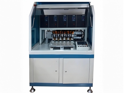
Bonding dwell and die temperature, not platen temperature, define whether the joint is fully cured. Equipment: AUTO Bonding Machine for Smart Card Modules.
Practical Rules That Keep the Joint Inside the Window
✓ Treat adhesive as a perishable
Silver-filled epoxy has a pot life measured in hours at room temperature and changes viscosity throughout it. Log thaw and open time, and reject material past its working window rather than topping up a syringe.
✓ Keep the bond line honest
A joint that is too thin has no compliancy and cracks under thermal cycling. One that is too thick has higher resistance and cures unevenly. The middle of the window is the design target, not the fastest achievable.
✓ Do not cure the card to cure the module
Localized bonding heats the module interface, not the whole card. If the card body has to survive the profile, check the body specification first: PVC softens well below typical cure temperatures, which is why dwell is short and localized.
✓ Qualify with thermal cycling, not with a pull test
A pull test measures the joint you made today. Thermal cycling measures whether the cure was complete, because incomplete epoxy keeps shrinking under cycling and the resistance drifts.
Reference Values for Flip-Chip ICA Bonding
Typical reference ranges for silver-filled isotropic conductive adhesive used on smart card modules. Exact values come from the adhesive supplier and must be validated on your own stack and dwell.
Where This Window Applies
The same cure logic governs any process where a filled adhesive forms both the mechanical and the electrical connection:
- Contactless and dual-interface module bonding to antenna pads
- Flip-chip assembly of secure elements onto inlay or lead frame
- Chip-on-board and chip-on-flex assemblies with silver-filled adhesive
- Repair and rework stations where a second cure passes over an existing joint
- Any line where first pass yield is high but field resistance drift appears after thermal cycling
Frequently Asked Questions
Why do modules pass at the line and fail in the field?
Because under-cured epoxy still conducts. The silver particles are in contact, so the electrical test passes. The matrix, however, has not finished reacting, and it continues to shrink and build stress through thermal cycling until the contact resistance climbs out of specification. The failure is delayed by design, not by chance.
Can a shorter dwell be recovered by raising the temperature?
Only within limits. Adhesives are usually rated for a peak temperature above which the cured matrix degrades or the card body deforms. If the die curve shows the required time above gelation is not met, extend the dwell or improve heat transfer through the tooling rather than pushing the set point.
Does the whole card need to go through the cure profile?
No. Bonding is localized, which is what makes short dwells possible on heat-sensitive card bodies. The relevant constraint is that the card body directly under the module must tolerate the local profile, and PVC in particular needs the dwell kept short enough that the body does not soften and lose cavity geometry.
Next Step
More equipment in this range is listed on the ZOWINDA CardMachine product page, and related application notes appear in our Industry News section.
Related reading:
- Printed Antenna Tolerance: Which Dimension Actually Moves Resonance
- Dual-Interface Ferrite: Why Sheet Thickness Beats Permeability on the Datasheet
- Automatic IC Module Testing Machine for Smart Card Production
- ICC Backside Spot Pressure Tester for Smart Card Quality Control
Ready to boost your production efficiency?
Contact us for a tailored solution and quotation on inlay production, card testing and personalisation equipment.
Email: info@zowinda.com
WhatsApp: +86 186 2085 0485
 Isotropic Conductive Adhesive
 Dual-Interface Ferrite: Why Sh
 Printed Antenna Tolerance: Whi
 Contactless Card Test Programm
Please contact us with your request
We are ready to answer your questions.