
Laser Cutting or Die Cutting: How the Cavity Edge Decides Card Reliability
Smart Card Manufacturing Notes
Laser Cutting or Die Cutting: How the Cavity Edge Decides Card Reliability
Published: November 16, 2026 | ZOWINDA Application Engineering
Every dual-interface and every hybrid card begins with a hole. The cavity that receives the module can be punched, milled or cut with a laser, and the choice is usually argued on throughput and tooling cost. That argument is correct and incomplete, because the two processes leave completely different edge populations, and the edge is what the module and the overlay have to bond to for the next ten years.
Two Ways to Open a Body, Two Edge Populations
Die cutting removes the cavity in one mechanical stroke. A hardened punch shears the card body against a die, and the quality of the cut is governed by clearance, which is normally set at a few percent of the body thickness. A fresh tool produces a clean edge with minimal burr. As the tool wears, clearance grows, the sheared zone gives way to a torn zone, and the edge acquires a burr on the exit side plus a whitened stress band on the entry side. On PVC the whitening is obvious in raking light; on polycarbonate it appears as a fine crazed band that is easy to miss and easy to propagate. The process is fast, cheap per card at volume, and blind to its own wear unless the tool is tracked by shot count.
Laser cutting removes material without contact, one pass or several, and it changes the edge chemistry rather than its geometry. The beam vaporises a kerf roughly one hundred to two hundred micrometres wide and leaves a heat affected zone around it that measures tens of micrometres. On PVC the consequence is material specific: PVC is more than half chlorine by weight, and the beam releases hydrogen chloride and tars at the cut. A correctly tuned process with extraction at the kerf produces a light amber edge that is cosmetically acceptable and structurally sound. An over-energised process produces a black, bubbled, carbonised edge that is friable, conductive in the worst case, and mechanically the worst possible surface to laminate onto.
The reason the edge matters is that a cavity is not a hole, it is a joint face. After implanting, the module has to sit coplanar with the card surface inside a tolerance that is typically under a tenth of a millimetre, and the adhesive or potting compound has to fill the gap between module wall and cavity wall without voids. A burr on the cavity floor lifts the module on one side, which converts a designed planar joint into a line contact. A carbonised or friable edge sheds particles into the bond line, and a crazed edge on polycarbonate becomes the initiation site for a crack that opens when the card is bent in a wallet. None of these defects is visible on a caliper measurement, which is precisely why cavity inspection that only checks dimensions passes bad cards.
The decision is therefore a tolerance question before it is a cost question. Cavity position and size tolerances in the range of plus or minus one tenth of a millimetre are reachable by both processes, but only die cutting keeps that tolerance at tens of thousands of strokes per hour, and only laser cutting reaches it without tooling at all. Where the cavity must be cut after lamination, after chip embedding, or in a body already carrying a printed inlay, mechanical punching is no longer an option because the punch loads the whole sheet and the punch cannot avoid the electronics. That is the boundary: die cutting for high volume cavities in bare bodies, laser cutting for small lots, thick or exotic bodies, post-lamination windows and anything that must avoid mechanical load.
How to Qualify an Edge Instead of a Dimension
- Write the edge specification as a profile, not a number. Specify burr height, whitening or char acceptance, taper and heat affected zone width separately for each material, and state the measurement method. A cavity drawing that only gives length, width and depth cannot be inspected for the defects that actually cause field failures.
- Run an energy ladder before accepting a laser recipe. Cut the same cavity at five combinations of power, speed and repetition rate, then section each card and measure kerf width, taper and heat affected zone on a micrograph. The usable window is the set of combinations where all three stay inside specification while the edge stays free of carbonisation.
- Track tool wear by shot count on a die. Record strokes per tool and inspect cavities at fixed intervals with a raking-light and a burr gauge. A punch that has produced a hundred thousand acceptable cavities will still produce rejects for the next ten thousand if nobody is watching the counter.
- Test the cavity card, not a blank card. Bending and torsion testing to the relevant card standard must be run on cards that carry a real cavity and a real module. A blank card has no stress riser at the cavity wall, so it will pass a bend that opens a microcrack from a crazed edge in production.
- Correlate edge quality with implant results. Measure module sitting height and coplanarity after implanting and plot it against the cavity batch. If coplanarity drifts with a new punch or a new laser recipe, the edge was the variable, and the implant station was never at fault.
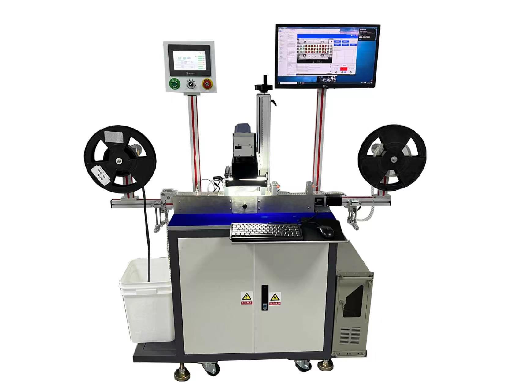
The kerf is a joint face, not just a hole: edge quality feeds module coplanarity and bond integrity. Equipment: Modules Laser Cutting Machine for Smart Card Modules.
Rules That Keep the Edge Under Control
✓ Match extraction to chemistry, not to smell
Laser cutting PVC releases hydrogen chloride that attacks optics and corrodes nearby mechanics. Extraction at the kerf is a process requirement, not a comfort measure, and a fume filter alone does not protect the machine internals.
✓ Keep the cut on the correct side of lamination
Cutting before lamination lets the overlay seal the cavity edge, which is the more forgiving route. Cutting after lamination exposes a raw edge and shifts the whole burden onto cut quality and post-cut cleaning.
✓ Treat whitening and char as separate defects
Whitening on PVC and polycarbonate is mechanical damage with a stress band. Char is thermal damage with altered chemistry. They have different causes, different fixes and different consequences for the bond line.
✓ Inspect cavities at the same rate as you inspect modules
Cavity defects are cheap to catch and expensive to trace. A go and no-go check plus a periodic section is a fraction of the cost of reclaiming cards that failed a bending test six months downstream.
Reference Values for Cavity Edges
Typical reference bands for 0.76 to 0.84 millimetre card bodies carrying a standard module cavity. Real limits depend on body material, overlay construction, laser wavelength and the coplanarity the implant station can absorb, and must be confirmed by sectioning your own production cards.
Where the Edge Question Applies
The same reasoning applies wherever a cavity, window or slot has to be opened in a laminated body that carries electronics:
- Dual-interface payment and transit cards with a milled or cut module cavity
- Hybrid cards combining a contact chip and a contactless inlay in one body
- Cards with milled windows for displays, fingerprint sensors or batteries
- Polycarbonate government documents where crazing at an edge propagates under bending
- Any body opened after lamination, where mechanical punching is no longer permissible
Frequently Asked Questions
Can a laser cut PVC cleanly enough to skip secondary cleaning?
Usually yes, if the recipe is tuned for the material rather than inherited from a polycarbonate job. The edge will show a light amber tint that is normal, but it must not be black, bubbled or powdery. Verify by wiping the edge with a white swab: transfer of dark powder means the process is over-energised and the edge will shed into the bond line.
Is laser cutting slower than die cutting in practice?
For a single cavity it is, often by an order of magnitude in cards per hour. The comparison changes when changeover is counted. A die needs a new tool for a new format and a setup you can measure in hours, while a laser needs a program and a focus check. Below a few thousand pieces per format, laser is frequently the cheaper route per good card.
Does cavity edge quality change the read range of the finished card?
Not directly, because the antenna sits away from the cavity wall. It changes reliability of the range over life. A burr that lifts the module changes the mechanical gap, a friable edge traps moisture, and moisture in a laminated body shifts the dielectric environment of the antenna, which shows up later as a card that resonates low and reads short.
Next Step
More equipment in this range is listed on the ZOWINDA CardMachine product page, and related application notes appear in our Industry News section.
Related reading:
- Dual-Interface Bridge: Making the Contact and Contactless Paths Agree
- Key Injection and Audit Trail: The Part of Personalisation That Gets Audited
- Modules Laser Cutting Machine - Smart Card Module Chip Singulation System
- Reel-to-Reel or Sheet-to-Sheet: Matching Inlay Architecture to Volume
Ready to boost your production efficiency?
Contact us for a tailored solution and quotation on inlay production, card testing and personalisation equipment.
Email: info@zowinda.com
WhatsApp: +86 186 2085 0485
 Key Injection and Audit Trail:
 Dual-Interface Bridge: Making
 Laser Cutting or Die Cutting:
 Reel-to-Reel or Sheet-to-Sheet
Please contact us with your request
We are ready to answer your questions.