
Smart Card Lamination Defect Prevention 2026 | Zowinda
Smart Card Lamination Defect Prevention 2026 | Zowinda
Published: 2026-08-19 | Zowinda Industry News
Smart card lamination is the stage where separately printed, personalized, and inlay-embedded sheets are fused into a single, durable card body. Get it right and the finished card survives years of daily flexing and tapping with stable electrical performance; get it wrong and you ship delamination, warping, and intermittent contactless reads that only surface after the cards reach the field. This guide walks through the process parameters, material layup, and inline controls that determine lamination quality, and shows how to prevent the defects that most often ruin a production batch.
Why Lamination Determines Card Reliability
Lamination is far more than cosmetic bonding. The laminate layers protect the printed artwork, fully encase the inlay antenna and the chip module, and fix the card's final thickness, flatness, and edge quality. A weak bond allows moisture and repeated flexing to separate the layers, which shifts the antenna geometry and degrades read range over time. Air gaps trapped during lamination act as insulators and reflect RF energy, producing dropped reads at the reader gate. Because these failures are invisible at the factory without proper testing, lamination discipline is the single most leveraged quality control point in the entire card manufacturing flow. A line can have a flawless printer and a precise personalizer, yet still ship defective cards if the laminator is out of specification.
Core Process Parameters: Temperature, Pressure, Dwell Time
Three variables dominate every lamination outcome. Temperature softens the adhesive and the PVC or PETG layers so they flow and fuse into one body; too low and the bond is incomplete, too high and the substrate yellows, the overlay hazes, or the inlay warps. Pressure drives out trapped air and forces full surface contact across the entire platen; insufficient pressure leaves micro-voids that become bubbles, while excessive pressure squeezes the inlay and distorts the antenna coil. Dwell time, how long heat and pressure are held, must be long enough for the adhesive to fully cure but short enough to protect heat-sensitive chips and keep throughput acceptable. Modern automatic laminators hold these three variables within tight, recipe-driven windows and log every cycle for traceability. The recipe is not universal: a PETG core demands a different profile than PVC, and a composite hybrid demands even tighter control, so each card construction needs its own validated recipe.
Material Layup and Adhesive Selection
The layup stack, top overlay film, printed layer, core sheet, inlay, core, and bottom overlay, must be matched to the adhesive system. Co-extruded overlay films with a compatible melt index bond cleanly to the core without bleeding or smearing the underlying print. PETG cores require different temperature and pressure profiles than PVC, and mixing incompatible films is a frequent cause of edge lifting and de-lamination at the card border. The adhesive layer, whether built into the overlay or applied separately, must wet both surfaces evenly. A documented layup recipe for each card construction removes guesswork and keeps batch-to-batch consistency, which is what lets a manufacturer reproduce a good card ten thousand times in a row rather than once.
Common Defects and How to Prevent Them
Delamination and edge lifting are usually caused by low pressure, contaminated or dusty surfaces, or an adhesive mismatch. Prevention starts with surface cleaning and a verified pressure curve, plus a layup recipe that matches the film system. Bubbles and white spots come from trapped air or moisture in the core; pre-baking cores, using vacuum or breathing cycles in the laminator, and controlling the heat ramp prevent them. Warping and thickness variation trace back to uneven temperature or pressure across the platen, which is solved by platen calibration and uniform stack loading rather than by adjusting the recipe. Yellowing or hazing is simply overheating and is corrected by recipe-limited temperature and a shorter dwell. Inlay shift and the resulting read failure come from excessive pressure bearing directly on the antenna; a pressure cap plus post-lamination RF verification catches this before the card advances. Each of these defects has a single dominant cause, which means each is preventable with a controlled, logged process instead of trial and error on the line.
Inline Quality Control for Lamination
The cheapest defect is the one caught before the next station. Inline checks at the laminator exit should include thickness gauging to confirm the card meets its tolerance, visual inspection for bubbles and edge lift, and RF read-range verification on a statistical sample or on every card depending on the application. Just as important is logging the lamination parameters, temperature, pressure, dwell, and recipe ID, for every batch so that any downstream read failure can be correlated back to a specific set of conditions. This turns quality from intuition into data. The strongest setup pairs the laminator with upstream personalization and downstream inspection inside one integrated production line, so a laminator fault is detected and stopped immediately rather than discovered after ten thousand cards have shipped.
How to Validate a New Lamination Recipe
Before committing a new card program to volume, the lamination recipe must be validated on sample runs. Run the target layup at the proposed temperature, pressure, and dwell, then measure bond strength, thickness uniformity, edge lift, and read range on the output. Compare against the specifications for the intended application, whether transit, payment, access control, or national ID, and iterate the recipe until every metric passes consistently. Document the final recipe as the production standard and lock it into the laminator so operators cannot drift from it. This validation step is what separates a line that merely runs from one that reliably yields good cards, and it should always precede equipment sign-off.
Lamination in the Full Production Line Context
Lamination does not stand alone. It sits between printing and personalization on one side and milling, embedding, and inspection on the other, and its output quality dictates how cleanly those later stations can work. A card that leaves the laminator flat, correctly bonded, and within thickness tolerance is easy to mill, easy to embed, and easy to inspect; a poorly laminated card creates rejects at every downstream gate. That is why serious buyers specify the laminator as part of a matched, integrated line rather than as a standalone machine, and why validating the lamination recipe is the first step in any new card program.
Conclusion
Lamination is the quiet determinant of whether a smart card lasts and performs in the field. Controlling temperature, pressure, and dwell, matching the film and adhesive system, preventing the common defects through a logged recipe, and verifying output inline turns lamination from a source of scrap into a reliable, repeatable process. For any new card program, validate the lamination recipe first, then build the rest of the line around it. Zowinda supplies matched laminators and complete integrated production lines so that bonding quality is engineered in from the start rather than inspected in after the fact.
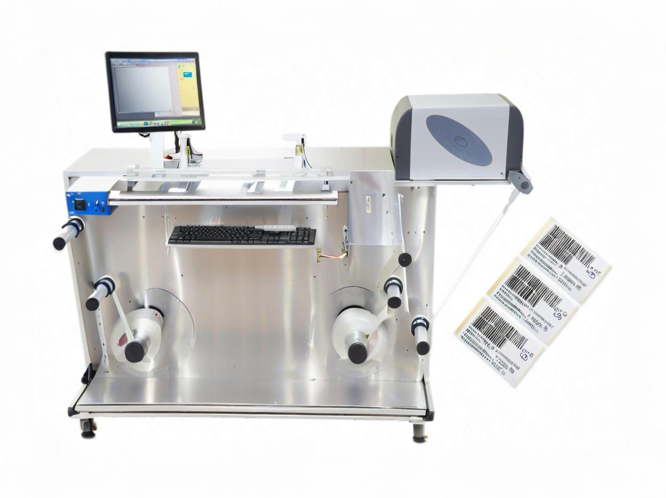
Zowinda smart-card production equipment on the manufacturing floor.
Key Advantages
✔ Bond Strength
Correct temperature and pressure produce a permanent, moisture-resistant layer bond.
✔ RF Stability
Gap-free lamination keeps the antenna geometry stable for reliable read range.
✔ Recipe Logging
Every cycle is logged by recipe ID for full batch traceability.
✔ Inline Gauging
Thickness and visual checks at the exit catch defects before the next station.
Technical Parameters
Frequently Asked Questions
What causes smart card delamination?
The dominant causes are low lamination pressure, contaminated or dusty surfaces before bonding, and an adhesive or film mismatch. Each is preventable: clean the surfaces, verify the pressure curve, and use a documented layup recipe matched to the film system. Logging every cycle makes any recurrence traceable to a specific batch.
What temperature is used for PVC versus PETG lamination?
PVC typically laminates in the 100-140 C range, while PETG needs a higher 120-160 C profile because of its different melt behavior. Composite hybrids demand even tighter control. The exact setpoint depends on the overlay and core combination, so each construction should have its own validated, locked recipe.
How do air bubbles form and how are they prevented?
Bubbles and white spots come from trapped air or moisture inside the core. They are prevented by pre-baking cores to remove moisture, using vacuum or breathing cycles in the laminator to evacuate air, and controlling the heat ramp so layers soften gradually rather than trapping pockets.
Can lamination affect contactless read range?
Yes. Air gaps or misalignment from poor lamination shift the antenna and weaken coupling, causing dropped reads. Clean, gap-free lamination is essential for stable read range, which is why post-lamination RF verification is a recommended inline quality gate.
Should lamination be part of an integrated line?
For volume programs it should. A laminator that is paired with upstream personalization and downstream inspection inside one integrated line detects and stops faults immediately, whereas a standalone laminator lets defects advance to later stations and become expensive rejects.
Related Equipment
Smart Card Lamination Machine » | Auto Contactless Card Inlay Line » | Smart Card Cavity Milling Machine » | Smart Card Production Line Buyer's Guide 2026 »
Need a reliable lamination or card production line?
Contact Zowinda for equipment selection, quotation and turnkey lines.
Email: info@zowinda.com
WhatsApp: +86 186 2085 0485
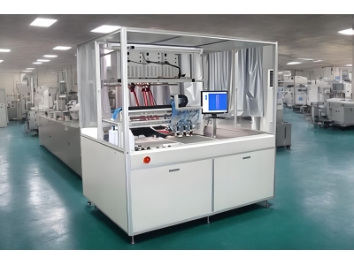 Revolutionizing the Contactles
 Auto Hole Punching Machine - T
 Partner 5
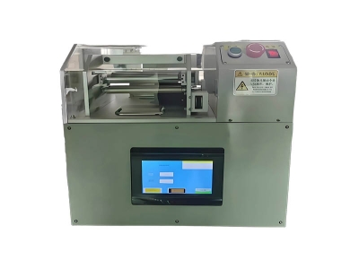 PT087 Passport Bending Fatigue
Please contact us with your request
We are ready to answer your questions.