
RFID Inlay Sample Bonding Machine Guide 2026 | Zowinda
RFID Inlay Sample Bonding Machine: A Lab-Grade Guide for 2026
Creating reliable RFID inlay samples is the first step toward high-volume tag, card, and label production. Whether you are validating a new antenna design, bonding a new chip footprint, or preparing small lots for pilot customers, the right RFID inlay sample bonding machine determines how fast your design moves from concept to qualified product. In this 2026 guide, Zowinda explains what an RFID inlay bonding machine does, which specifications matter most, and how a precision bonding platform fits R&D labs and small-batch manufacturing workflows.
What Is an RFID Inlay Sample Bonding Machine?
An RFID inlay sample bonding machine is a compact, precision assembly system used to attach RFID chips to antennas on PET, PVC, or paper substrates. The process is also called flip-chip bonding, die bonding, or inlay lamination, depending on the adhesive and pressure method used. Unlike full-scale production lines that bond millions of inlays per year, a sample bonding machine is built for flexibility: engineers can swap chip trays, adjust pressure, change temperature profiles, and test different antenna materials without committing an entire production module to one recipe.
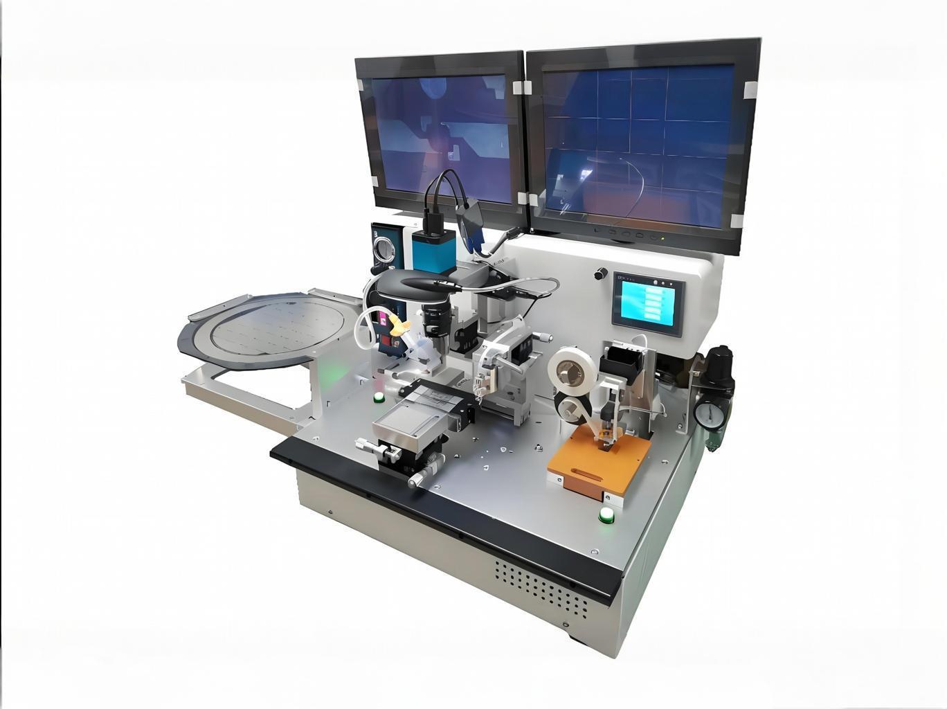
The Zowinda RFID inlay bonding machine is designed specifically for laboratory use, prototyping, and low-volume production. It combines a PLC-controlled motion platform, dual visual positioning cameras, and adjustable heat-press bonding to deliver repeatable results across UHF and HF inlay designs. Because sample bonding directly influences read range, mechanical durability, and yield in later mass production, many RFID converters use the same machine both for first-article validation and for small-lot custom orders.
In practice, the workflow starts with an antenna sheet loaded onto the bonding stage. The operator places a tray of bare RFID chips or picks chips from an 8-inch wafer. The machine cameras locate the antenna pads and chip bumps, the motion head places the chip, and the heat press applies controlled force and temperature for a programmed dwell time. After bonding, the inlay can be laminated, die-cut, or sent directly to an RFID test encoder to verify read performance.
Key Specifications and Performance Data
The following table summarizes the core technical data for the Zowinda RFID inlay sample bonding machine. Use these numbers when comparing laboratory bonding platforms or writing equipment qualification documents for your facility.
| Parameter | Specification |
|---|---|
| Equipment size | 640 mm (L) x 460 mm (W) x 620 mm (H) |
| Weight / power | 35 kg / 200 W |
| Pressure setting | 60 g to 200 g, error margin 0.05 N |
| Bonding temperature | 50 degC to 250 degC, touch-screen adjustable |
| Supported chip sizes | 0.3 mm x 0.3 mm to 2.5 mm x 2.5 mm (UHF and HF) |
| Chip loading | Tray loading or manual loading from 8-inch wafer |
| Antenna loading | Manual feeding; compatible with PET, PVC, and paper |
| Antenna sheet size | Up to 120 mm x 100 mm |
| Visual positioning | 2 camera systems for chip-to-antenna alignment |
| Patch accuracy | 25 micrometers |
| Control system | PLC + touch screen, 220 VAC power supply |
| Adhesive compatibility | Anisotropic conductive adhesive (ACA) and heat-press films |
These specifications make the machine suitable for precise bonding of RFID inlays during sampling, prototyping, and short-run production. The 25 micrometer placement accuracy and 0.05 N force resolution are especially important for small UHF chips, where even a slight offset can shift resonance frequency and reduce read distance.
Why Precision Bonding and Material Compatibility Matter
RFID inlay performance depends on a stable electrical and mechanical connection between the chip bump pads and the antenna terminals. If the bond is too weak, the joint can crack during lamination, card punching, or daily flexing. If the pressure is too high, the chip or substrate may fracture, causing intermittent reads or complete failure. A laboratory-grade RFID inlay bonding machine gives engineers closed-loop control over pressure, temperature, time, and placement so they can find the process window that maximizes yield without damaging delicate components.
Material compatibility is equally important. The Zowinda sample bonder accepts PET, PVC, and paper antenna substrates up to 120 mm x 100 mm. PET offers good dimensional stability for high-frequency inlays, PVC is common in card applications, and paper is widely used for logistics labels and sustainable packaging trials. Supporting all three materials in one benchtop unit means a single R&D team can evaluate multiple market segments without investing in separate bonding tools.
Temperature flexibility adds another layer of experimental freedom. The 50 degC to 250 degC range covers most thermoset and thermoplastic adhesives used in RFID assembly. Engineers can run design-of-experiments (DOE) on cure temperature, dwell time, and cooling rate to optimize pull strength, contact resistance, and read range before transferring the recipe to a production line.
How to Build a Sample Bonding Recipe
A repeatable bonding recipe ties together five variables: substrate type, adhesive selection, placement accuracy, bonding force, and thermal profile. The Zowinda machine lets you adjust each variable independently, which is essential when moving from one inlay design to another.
Start by defining the chip and antenna geometry. Measure the bump pad locations on the chip and match them to the antenna terminal layout. Enter these coordinates into the PLC interface and use the two-camera vision system to teach the reference points. Next, select the adhesive. Anisotropic conductive adhesive (ACA) is the most common choice because it conducts electricity only in the vertical direction between the chip bump and antenna pad while remaining insulating laterally. The amount of adhesive, its storage temperature, and its cure schedule all affect final contact resistance.
Force and temperature are then optimized as a pair. Too little force leaves air gaps and high resistance; too much force squeezes adhesive out of the bond area and can short adjacent pads. The 60 g to 200 g force window on the Zowinda machine, combined with 0.05 N resolution, gives enough resolution to find the correct value for most UHF and HF chips. Temperature is ramped to the adhesive manufacturer recommended cure point, held for the recommended dwell time, and then cooled before releasing pressure. Document every parameter so the recipe can be reproduced on the production floor.
After bonding, samples should be checked for contact resistance, shear strength, and RFID read range. A well-developed sample bonding recipe will show stable read performance across temperature cycles and mechanical flex tests. Because the Zowinda machine delivers repeatable placement and force, bonded samples can serve as golden reference units when qualifying production lots or comparing adhesive suppliers.
Applications: R&D Labs and Small-Batch Production
The primary users of an RFID inlay sample bonding machine are R&D departments, quality labs, and small-lot converters. Typical applications include:
- New product introduction (NPI): Bond first-article samples of new chip-antenna combinations for electrical validation and environmental testing.
- Material qualification: Compare different substrates, adhesives, and chip suppliers under identical bonding conditions.
- Customer samples: Produce 10 to 1,000 custom inlays for pilot deployments in retail, logistics, access control, or healthcare.
- Failure analysis: Reproduce production defects on a controlled benchtop system to identify root causes related to pressure, temperature, or alignment.
- Training and documentation: Use the machine to train operators and capture standard operating procedures before scaling to automated production.
Because the machine occupies only 640 mm x 460 mm of bench space and weighs 35 kg, it fits comfortably in most labs. The 220 VAC single-phase power requirement avoids the three-phase infrastructure often needed by larger production bonders.
Related ZOWINDA RFID Equipment
Sample bonding is one stage of a complete RFID inlay workflow. Zowinda offers several complementary machines that help converters move from raw materials to finished cards or labels:
- All-in-One RFID Inlay Machine - combines multiple inlay production steps in one platform for medium-volume manufacturing.
- RFID Automatic Flip Chip System - high-speed pick-and-place bonding for production-scale UHF and HF inlay output.
- RFID Label Detecting and Encoding Machine Guide - learn how to test, encode, and verify RFID labels after bonding.
Together, these systems cover sampling, bonding, encoding, and quality control so you can scale from prototype to production without changing equipment vendors.
Frequently Asked Questions
Q1: What is an RFID inlay sample bonding machine used for?
A: It bonds RFID chips to antennas on PET, PVC, or paper substrates for sampling, prototyping, and small-batch production. It is commonly used in R&D labs to validate new inlay designs before mass production.
Q2: What chip sizes and frequencies does the Zowinda machine support?
A: The machine supports chip sizes from 0.3 mm x 0.3 mm up to 2.5 mm x 2.5 mm for both UHF and HF RFID applications.
Q3: How accurate is the bonding placement?
A: The dual visual positioning system achieves 25 micrometer patch accuracy, which is sufficient for small UHF chips and fine-pitch antennas.
Q4: Can I use this machine for materials other than PET?
A: Yes. The manual antenna feeding system supports PET, PVC, and paper substrates up to 120 mm x 100 mm.
Q5: Is the machine suitable for production use or only for samples?
A: It is optimized for laboratory, prototyping, and small-batch work. For high-volume production, Zowinda recommends the RFID Automatic Flip Chip System.
Get a Quote for Your RFID Inlay Sample Bonding Machine
If you need a reliable RFID inlay sample bonding machine for your R&D lab or small-batch production line, Zowinda can help. Contact us today for a quotation, technical datasheet, or video demonstration.
Email: [email protected]
WhatsApp: +86 186 2085 0485
 Edge-to-Edge Printing vs Borde
Card Stacking and Banding vs T
Hot-Stamping Foil vs Digital F
In-Mold Foil Decoration vs Pos
Edge-to-Edge Printing vs Borde
Card Stacking and Banding vs T
Hot-Stamping Foil vs Digital F
In-Mold Foil Decoration vs Pos
Please contact us with your request
We are ready to answer your questions.