
Dual-Interface Smart Card Cavity Milling: Complete Technical Guide for 2026
Dual-Interface Smart Card Cavity Milling: Complete Technical Guide for 2026
Published: 2026-08-01 | Zowinda Card Machine Technical Series
Dual-interface smart cards -- combining contact chip and contactless RFID antenna in a single card body -- represent one of the most technically demanding segments of modern smart card manufacturing. The cavity milling process, which precisely machines a recess into the card substrate to embed the contact module without damaging the underlying antenna coil, requires specialized CNC equipment with micron-level accuracy. This comprehensive guide covers everything production managers need to know about cavity milling technology in 2026.
What is Dual-Interface Cavity Milling?
Dual-interface (DI) cards, also known as combi-cards, integrate both a ISO 7816 contact chip and an ISO 14443 contactless antenna. The critical challenge lies in the cavity milling step: a precision CNC router must mill a precisely dimensioned recess into the laminated card body where the contact module will be later embedded (via the implanting process). The depth tolerance is typically +/- 0.02mm, and the milling path must avoid severing the antenna coil embedded just 0.15-0.25mm beneath the surface.
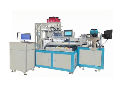
Modern cavity milling machines like the Zowinda P191 Smart Card Cavity Milling Machine employ closed-loop servo positioning systems with optical encoders achieving repeatability within 5 microns. The milling head typically uses a 2-flute carbide micro-endmill rotating at 30,000-50,000 RPM, with real-time force monitoring to detect antenna contact before damage occurs.

Figure 1: Precision CNC cavity milling machine for dual-interface smart card production
Key Technical Parameters for Cavity Milling
Critical Process Considerations
Antenna Protection
The milling tool must stop precisely above the antenna coil. Advanced machines use acoustic emission sensors and motor current monitoring to detect incipient antenna contact before the coil is severed.
Chip Removal
Vacuum extraction integrated into the milling head removes PVC dust in real-time. Residual chips cause defects during subsequent module implanting and lamination steps.
Tool Wear Monitoring
Automated tool wear compensation adjusts Z-axis offset as the cutting edge dulls. Out-of-spec tools are flagged before they produce out-of-tolerance cavities.
Multi-Cavity Support
Production-grade machines support multiple cavity profiles (ISO 7816 ID-1, ID-000, custom) with quick-change fixture systems under 60 seconds.
Milling vs. Punching vs. Laser Ablation
Three competing technologies exist for creating the module recess:
- CNC Milling: Highest precision, lowest cost per card at scale, established technology. Dominates over 85% of DI card production worldwide.
- Punch/Die-cutting: Fastest cycle time under 1 second, but limited to fixed cavity shapes. Tooling cost is high for custom profiles.
- Laser Ablation: No mechanical contact (zero antenna risk), but slower (3-5s/card) and higher capital/operating cost. Growing niche in premium segments.
For most production environments processing over 500 cards/hour, CNC milling remains the optimal choice when balancing precision, speed, and total cost of ownership.
Selection Checklist for Cavity Milling Equipment
- Verify position repeatability specification (target: less than or equal to 5 microns)
- Confirm antenna detection sensor type (acoustic emission preferred)
- Check maximum spindle speed (higher equals cleaner cuts, longer tool life)
- Evaluate changeover time between cavity profiles
- Review dust extraction efficiency rating
- Request reference installations in similar production volumes
- Validate after-sales service and spare parts availability in your region
Looking for a Reliable Cavity Milling Solution?
Contact our engineering team for technical consultation, equipment demos, and customized quotes for your production requirements.
Email: [email protected]
WhatsApp: +86 186 2085 0485
 RFID vs NFC Smart Cards: Compl
 Statistical Process Control fo
Hydraulic vs Servo-Electric La
Smart Card Module Embedding: C
Statistical Process Control fo
Hydraulic vs Servo-Electric La
Smart Card Module Embedding: C
Please contact us with your request
We are ready to answer your questions.