
Integrated Inlay Manufacturing System: Complete Guide to RFID Inlay Production Equipment
Integrated Inlay Manufacturing System: The Complete Guide to All-in-One RFID Inlay Production Equipment
Published: July 17, 2026 | Category: Smart Card Production Line
The demand for RFID-enabled products has grown exponentially across supply chain management, contactless payments, access control, and IoT applications. At the heart of every RFID tag lies the inlay -- a precisely engineered assembly of an antenna pattern and an integrated circuit (IC) chip mounted on a carrier substrate. Traditional inlay manufacturing requires multiple standalone machines arranged in sequence, consuming significant floor space and introducing potential quality gaps between process steps. The Integrated Inlay Manufacturing System addresses these challenges by consolidating the entire inlay production workflow into a single, synchronized platform.
What Is an Integrated Inlay Manufacturing System?
An Integrated Inlay Manufacturing System is a comprehensive production line that combines multiple critical stages of RFID inlay fabrication into one unified equipment platform. Rather than operating separate machines for antenna patterning, chip attachment (die bonding), encapsulation, testing, and sheet formatting, manufacturers can now run the complete workflow within a compact, automated cell.
The system integrates precision mechanical modules with advanced optical alignment systems, computerized process control, and real-time quality monitoring. This integration reduces material handling between stations, minimizes contamination risk, shortens production cycle times, and ensures consistent output quality across high-volume batches.
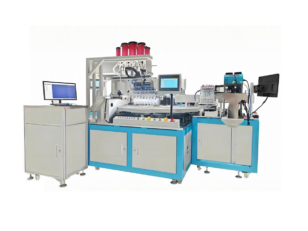
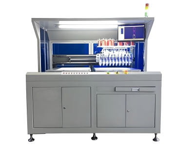
Figure 1: Integrated Inlay Manufacturing System showing the unified production platform for end-to-end RFID inlay fabrication
Key Features and Capabilities
Unified Process Control
A single HMI (Human-Machine Interface) controls all production modules. Operators monitor real-time status, adjust parameters, and view yield statistics from one touchscreen panel. This centralized control eliminates the complexity of coordinating multiple independent machines.
Precision Antenna Patterning
The system supports etched aluminum, printed silver ink, and vapor-deposited aluminum antenna patterns. High-accuracy positioning ensures consistent trace width and spacing tolerances critical for RF performance at UHF and HF frequencies.
Automated Die Bonding
High-speed pick-and-place heads attach IC chips to antenna connection pads with micron-level placement accuracy. The system handles various package formats including flip-chip, sawn-die, and strap-based attachments used across different inlay designs.
In-Line Testing Module
Built-in electrical testers verify each inlay's resonance frequency, return loss, and protocol response before the sheet proceeds to downstream operations. Defective units are automatically marked or removed from the production stream.
Technical Specifications
Production Workflow Overview
The integrated system processes raw materials through a carefully orchestrated sequence:
- Substrate Feeding: PET or paper carrier sheets are loaded into the input magazine. Automatic feeding mechanisms advance sheets through the line with precise registration marks.
- Antenna Fabrication: Pre-patterned antenna sheets enter the system. If using inline printing, conductive ink is jet-printed and cured before proceeding to chip attachment.
- Die Bonding Station: Vision-guided pick-and-place units position IC chips onto designated bond pads on each antenna. Conductive adhesive or anisotropic film creates reliable electrical connections.
- Curing / Encapsulation: A controlled thermal or UV curing stage solidifies the chip attachments. Optional overlay films provide environmental protection for demanding applications.
- Electrical Testing: Every inlay undergoes frequency response verification. Test results are logged per unit for full traceability.
- Sheet Formatting: Finished inlay sheets are slit, punched, or rolled onto output spools ready for conversion into labels, cards, or packaging inserts.
Why Manufacturers Choose Integrated Systems
The shift toward integrated inlay manufacturing reflects several industry trends that favor consolidated production cells over traditional multi-machine layouts:
- Floor Space Optimization: A single integrated footprint replaces 4-6 separate machines, reducing factory space requirements by up to 60%. This is particularly valuable for facilities expanding RFID capacity without building additional clean rooms.
- Reduced Work-In-Progress Inventory: With all process steps connected in-line, partially completed inlays do not accumulate between machines. This lowers carrying costs and reduces the risk of damage during inter-station handling.
- Consistent Quality: Automated handoffs between modules maintain tighter process control than manual transfer between standalone stations. Statistical data shows integrated lines achieve 2-3% higher first-pass yields compared to equivalent discrete machine setups.
- Easier Maintenance and Training: One system means one maintenance schedule, one spare parts inventory, and a single operator training program. Technical staff become proficient faster when managing a unified platform.
- Data Integration: All process parameters, test results, and yield metrics feed into a common database. Manufacturers gain end-to-end visibility for continuous improvement initiatives and customer quality audits.
Applications Across Industries
Inlays produced on integrated manufacturing systems serve diverse market segments:
Retail & Apparel
Inventory tracking labels, anti-theft EAS/RFID combo tags, size and price labeling
Logistics & Supply Chain
Pallet tags, case-level tracking, cold chain monitoring labels
Contactless Payment
Bank card inlays, transit ticket inlays, payment sticker form factors
Access Control & ID
Hotel key cards, employee badges, secure credential inlays
IoT & Asset Tracking
Sensor-enabled smart labels, NFC product authentication tags
Automotive & Manufacturing
Tire embedding inlays, assembly line WIP tracking tags
Selection Criteria: What to Evaluate Before Purchasing
When evaluating an integrated inlay manufacturing system for your production facility, consider the following decision framework:
Maintenance and Operational Best Practices
To maximize uptime and extend the service life of your integrated inlay manufacturing system, implement these operational practices:
- Daily Calibration Checks: Run calibration verification routines at the start of each shift. Verify vision alignment accuracy and die placement repeatability using standard reference samples.
- Preventive Component Replacement: Follow the manufacturer's recommended schedule for replacing wear items such as bonding tips, pick-up nozzles, and conveyor belts. Proactive replacement avoids unplanned downtime.
- Clean Room Discipline: Maintain appropriate particle counts in the production area. Dust and debris are leading causes of open-circuit defects in antenna traces and poor die-bond adhesion.
- Software Updates: Keep the system controller firmware and HMI software current. Updates often include process optimizations, new chip profile support, and diagnostic improvements.
- Data-Driven Tuning: Review SPC charts weekly to identify drift trends before they impact yield. Adjust process parameters proactively based on statistical evidence rather than reactive firefighting.
Ready to Streamline Your Inlay Production?
Contact our team for a customized quote, technical consultation, or on-site demonstration tailored to your production requirements.
Email: [email protected]
WhatsApp: +86 186 2085 0485
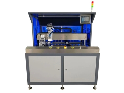 Auto COB Pick and Placer Machi
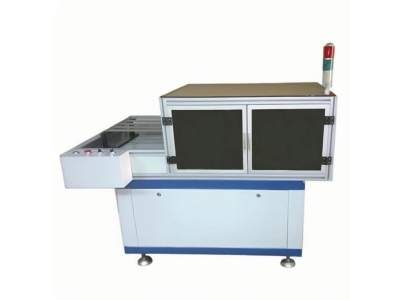 Auto Hole Punching Machine – P
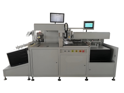 Auto Sheet Shearing Machine -
 Auto Antenna Embedding Machine
Please contact us with your request
We are ready to answer your questions.