
Antenna Impedance Matching for RFID Inlays: Tuning Methods and Yield Impact
Antenna Impedance Matching for RFID Inlays: Tuning Methods and Yield Impact
Publish date: 2026-09-02
An RFID inlay only reaches its rated read range when the antenna impedance is matched to the chip input impedance. Mismatch wastes transmitted power, shrinks read distance, and shows up as intermittent failures during final test. This guide reviews the practical tuning methods used on production lines and how each one affects yield.
Why Impedance Matching Determines Read Range
The transponder chip presents a complex input impedance that varies with frequency, temperature, and the dielectric properties of the card body. When the antenna is not conjugate-matched to that impedance, part of the incoming RF energy is reflected instead of harvested, so the chip needs a stronger field to wake up. In practice a mismatch of a few ohms can cut usable read range by a third, which is enough to fail an acceptance test even though every component is individually within specification.

Network analyzer measuring inlay antenna impedance before production release.
Production Tuning Methods
Geometry trimming
Adjusting loop width, stub length, or the inductive coupling gap shifts the resonant point without new tooling, making it the fastest correction during pilot runs and material changeovers.
Dielectric compensation
Because PVC, PET-G, and composite cores have different permittivity, the antenna pattern is re-tuned whenever the card material changes, preventing a silent read-range loss after a substrate switch.
Tuning Reference Parameters
Ready to improve your production efficiency?
Contact us for a tailored solution and quotation
Email: info@zowinda.com
WhatsApp: +86 186 2085 0485
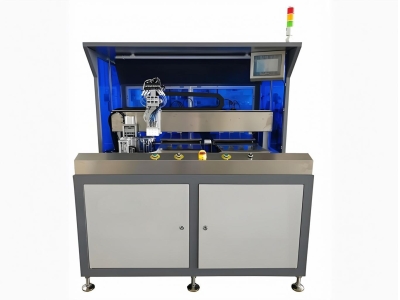 Auto COB Pick and Placer: Revo
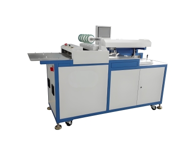 Auto Green Tape Dispensing Mac
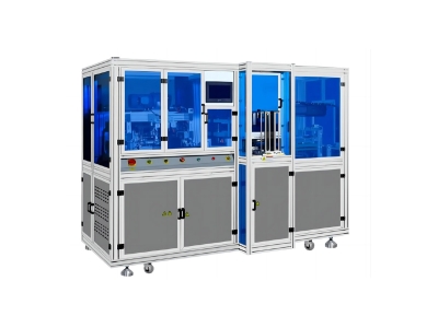 Automatic Sheet Collating and
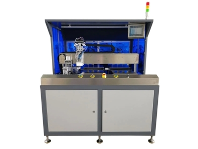 Auto COB Pick and Placer Machi
Please contact us with your request
We are ready to answer your questions.